History of Electrical Systems and Cables
Insulators Home > Book
Reference Info > History of Electrical Systems and Cables
Information from:
- Dunsheath, Percy. A History of Electrical Power Engineering.
Cambridge, MA (Printed in Great Britain): The M.I.T. Press. Copyright 1962.
LOC TK15.D8.
- Black, Robert Monto. The History of Electric Wires
and Cables. London, England: Peter Peregrinus Ltd (in association
with the Science Museum of London). Copyright 1983. ISBN 0863410014, LOC TK3301.B564.
- McGraw-Hill Book Company. Electrical Maintenance and
Repair: Wiring Diagrams of Electrical Apparatus and Installations.
York, PA: Maple Press. Copyright 1913. LOC TK3205.W6.
- Michael, Donald T (Working Group Chairman). IEEE
Recommended Practice for Electric Power Distribution for Industrial Plants,
5th Edition. New York, NY: Institute of Electrical and Electronics
Engineers, Inc - Standards Board. Copyright 1976. ISBN 0471026867, LOC TK3141.I18.
See the Timeline of Related Developments
for additional information.
This information comes from
- Dunsheath, Percy. A History of Electrical Power Engineering. Cambridge,
MA (Printed in Great Britain): The M.I.T. Press. Copyright 1962. LOC TK15.D8.
The 'Acknowledgements' states:
[...] Illuminations have been generously provided by industrial concerns
as the individual acknowledgements will indicate, and special thanks are due
to the assistance given by Dr. Follett, the Director of the Science Museum,
and his staff, one of whom, Miss Weston, has made many valuable suggestions.
The collection of historical material and confirmation of dates have been
greatly facilitated by the willing help given by the Librarian and Staff of
the Institution of Electrical Engineers. In particular, Mr. H. Lansley has
been tireless in his responses to my many calls on him. Friends in the Supply
Industry have also been most helpful in producing information on early power
stations, much of the information being channelled through Mr. P. A. Lingard
of the London Electricity Board. [...] The many cases of help received from
the light current, heavy current, and instrument sides of the elctrical industry
and from the electrical press are too numerous to permit a mention by name,
but to all I express my most grateful thanks.
The 'Preface' states:
[...] In the introduction to his History of the Institution of Electrical
Engineers, Mr. Rollo Appleyard, writing of the evolution of the Institution
from the former Society of Telegraph Engineers and Electricians, says, "It
has stood at the confluence of the streams of academic and practical knowledge
where for fifty years it has directed and safeguarded electrical progress."
[...] The history of such a subject as electrical engineering does not follow
a simple straightforward list of dates. The contributions of one man may continue
over many decades during which period others pick up the same threads to weave
completely different patterns. [...]
The following information is excerpted from this book.
Origins
[...] It is safe to assume that the first electrical effects to be noticed
by man were the lightning flash and the aurora borealis. Their existence called
for no deliberate act on his part, and they occurred long before he had produced
electrical charges himself, either fortuitously or by design. At first they
and their effects were completely out of man's control, though several thousand
years ago damage to buildings by lightning strokes was prevented by the nature
of their construction. Several famous historic buildings, including the Temple
of Juno and Solomon's Temple, had their roofs covered with metallic points
- sword blades or sharp ornamental objects - with resulting immunity to damage
by lightning. [...]
It was not until the great Benjamin Franklin, American writer, philosopher,
and statesman, became interested in electrical phenomena, that the idea of
deliberate protection of buildings emerged. After his famous and extremely
dangerous experiemnts of collecting electric charges by sending kites up into
thunderclouds, Franklin, in 1750, conceived the idea of a lightning conductor,
and in his Poor Richards Almanac for 1753, he puts forward the proposal
for the protection of buildings 'from mischief by thunder and lightning'.
[...]
The first half of the eighteenth century saw many discoveries and applications
of electricity. Outstandin among these was the principle of conduction and
insulation enunciated by Stephen Grey in 1720. By suspending a hempen line
on silken threads, he transmitted electric charges hundreds of feet. When
metallic wire was substituted for the hempen cord, circuits up to several
miles were made to carry the charge.
The French scientist Dufay seems to have been the first to have established
the idea that electricity appeared in two distinct forms, vitreous
and resinous, the former produced on glass, and certain other materials,
and the latter on amber, silk, paper, etc. He also observed that each repels
its own kind and attracts the other. [...]
The English scientist Dr. Watson made many experiemtns with the Leyden jar,
established the idea of two coatings separated by the dielectric, and spoke
of 'plus' and 'minus' electricity. With others, he also made long circuits
up to several miles, and discharged the Leyden jar through them. [...]
Birth of the Electric Telegraph
[...] The employment of magnetic and electrical effects for the transmission
of intelligence had been predicted long before the advent of the steady current
had provided a sound foundation for practical application. [...]
During the early half of the eighteenth century, a good deal of experimenting
was carried out by Stephen Gray, a Charterhouse pensioner, while Dr. Watson,
a member of a Royal Society Committee, brought to light the essential difference
between conductors and insulators. It was discovered that a damp hempen cord
suspended by silk loops could be made to transmit a static charge from a Leyden
jar. With a metallic wire so supported, the results were still more effective,
and a circuit was set up in July 1747 across the Thames over old Westminster
Bridge. The circuit was completed through the body of an assistant, who held
the far end of the wire in one hand, and with the other touched the water
with a metal rod. His reaction completely vindicated the result which had
been anticipated. Other experiments followed in various parts of London, and
the length of the circuit increased to several thousand feet. Franklin in
1748 in Philadelphia, and De Luc in 1749 in Switzerland, extended the range
but remarkable as it seems today, there was no suggestion of the discoveries
being applied to telegraphy. [...]
A rather fantastic suggestion was made in 1795 by a Spaniard, Salva, who
employed twenty-two pairs of wires for a twenty-two letter alphabet. At the
receiving end, each pair was held by a man who called out his letter when
he felt the shock. In due course, Salva resorted to simpler detectors in the
form of tinfoil plates and reduced the number of wires. [...]
Francis Ronalds moved to the house now known as Kelmscott House in Upper
Mall, Hammersmith, and it was here that he constructed the telegraph system
through which his name became so famous. The best description of his achievement
is contained in a small book which he published in 1823 and reprinted in 1871,
from which it is clear that his first concern was whether the electric fluid
in its static form could be made to travel over long distances without undue
delay. For this purpose, in 1816 he set up two wooden structures in his garden,
twenty yards apart, between which he strung iron wire backwards and forwards,
forming a continuous length of more than eight miles. The wire was insulated
at the 37 hooks on each of the 19 bars at both ends by silken loops, and the
two ends brought out to two pith-ball electrometers. [...]
The event which, more than any other, brought the telegraph to the notice
of the public, was the arrest in 1842 of the murderer Tawell at Paddington
Station. Mr. John Tawell, a respectable resident of Berkhamsted, was known
by the police to be in the habit of visiting a woman, Sarah Hart, at her home
near Slough. Early one morning she was found dead, and a man had been seen
leaving her home in rather suspicious circumstances some time before. On enquiry
at the Great Western station, they learned that a man answering to their description
had just gone off by the slow train to London. "But," said the inspector,
"why not try this new telegraph?" At once the message was sent indicating
that the man wanted was dressed as a Quaker with a brown coat reaching almost
to his feet. There seems ot have been some delay, owing to the fact that the
five-needle instrument had no signal for Q, and KWAKER was not at once understood.
When Tawll stepped out of the train at Paddington, however, he was shadowed
to a New Road omnibus and ultimately arrested. In due course, he was tried
for the murder and executed. The excitement, first over the manner of his
arrest, and secondly through startling revelations of his past career, seems
to have done as much, if not more, for establishing the telegraph of Cooke
and Wheatstone, than all their technical and business ability. Joint stock
companies were set up to exploit the invention for commercial purposes - The
Electric Telegraph company, which paid Cooke and Wheatstone £33,000
for their invention; the Magnetic Telegraph Company, and others - so that
by 1868, over 16,000 miles of telegraph line had been erected. By 1870, the
systems had been incorporated into one national undertaking, and taken over
by the Post Office.
The early lines were crude in the extreme, and the five wires for the Euston-Chalk
Farm circuit were carried in longitudinal grooves cut in the top and sloping
sides of wooden bearers. In consequence, electrical failures were common.
One of these, on the Fenchurch Street - Blackwell line, proved, according
to Fleming, the direct cause of a great improvement in the needle system.
There out of the five wires broke down, and the telegraph clerks devised a
code which enabled them to continue working with only two needles in use.
Finally it was found that one needle was all that was required. When the movement
of the needle was restricted by stops on the dial, a convention of 'dots'
to the left and 'dashes' to the right was adopted, so that various combinations
of dots and dashes gave all the letters and figures required. [...]
Morse was fortunate in enlisting [...] a young man, Alfred Vail, of a mechanical
turn of mind, who not only co-operated in the design and in making equipment,
but, what was even more vital at this time, secured financial backing. On
3 October 1837, Morse obtained his patent, and Vail improved the printer so
that it produced clear dots and dashes. The Morse Code, so well known by the
name of the inventor, seems really to have been the work of Vail, for we read
"Vail tried to compute the relative frequency of all the letters, in
order to arrange his alphabet; but a happy idea enabled him to save his time.
He went to the office of the local newspaper, and found the result he wanted
in the type-cases of the compositors." Thus was established the Morse
Code, which has survived for so long and in so many forms of signalling.
After four years of political string-pulling, frustration, and living on
the verge of starvation, Morse had his system approved by Congress, and he
received an appointment with a salary of $2,500 a month to superintent the
erection of a line connecting Baltimore and Washington. Serious difficulties
arose with underground conductors, but a conductor on poles was carried through,
and on 23 May 1843, messages were transmitted by Morse from the Capitol and
received by Vail at Baltimore. The line was opened on 1 April 1845 as a public
service, and after the Postmaster-General of the day had declined to purchase
the invention for $100,000, Morse proceeded to secure the support of private
enterprise. The Western Union amalgamated some of the earlier participants
in the venture, and went ahead in stretching a network of circuits over the
United States, the most dramatic of which was the New York to San Francisco
line completed in 1861. [...]
Electricity Supply
[...] In the year 1883, an enterprise was started in the West End of London
which, although originally intended as a local private lighting installation,
ultimately developed into an outstanding example of public electricity supply,
and one of great technical and engineering interest. As such, the Grosvenor
Gallery installation in New Bond Street will always rank as a pioneer in public
supply systems. [...] The lighting of the gallery was by arc lamps on a series
circuit with an automatic regulator maintaining a steady current of ten amperes,
and gave such satisfaction that requests for supply soon began to come in
from neighbouring residents and shopkeepers. Under a new Act, the Grosvenor
Gallery Company sought and obtained the permission of the local Authority
to run overhead lines across the roofs of houses, carrying the high tension
current. Each consumer was provided with a small transformer, the primary
windings of several being connected in series on the 2,000-volt supply circuit.
THe voltage was later raised to 2,400. [...]
Within a very few months, the system stretched from the Thames to Regents
Park, and from Knightsbridge to the Law Courts. Hundreds of iron posts fixed
on the roofs of houses carried rubber insulated conductors supported on steel
suspension wires by leather thongs. [...]
The release of capital by the 1888 Amending Act resulted in the inauguration
of many new supply systems both in London and in the Provinces. By the end
of the century, there were something like thirty power stations in London
alone, under the control of sixteen undertakings, most of them private companies.
[...] Having no power to open up the streets for underground mains, [companies]
carried their distribution circuits on overhead lines erected over the roofs
of houses. [...]
Alternating Current
The phenomenal growth of electrical engineering during the last two decades
of the nineteenth century, which had followed the introduction of the incandescent
lamp, left the supply industry in a curious state of uncertainty on an important
and much debated issue. [...] Namely, should the current, when generated mechanically,
be continuous or alternating? The experts, ranging themselves into two opposing
camps, debated the question hotly for many years. As we know today, the exponents
of the alternating system ultimately held the field, and development followed
this course. The direct current enthusiasts, however, made such progress over
the years in carrying their ideas into effect that even now (1960), over half
a century later, there are still vestiges of D.C. sections remaining, though
they are rapidly approaching extinction. [...]
The direct current engineers, from the very beginning, appreciated that the
extension of a system beyond the immediate surroundings of the generating
station raised the question of economy in cost of the mains and the control
of the drop in voltage at the end of long sections with increasing load. They
saw that to overcome this difficulty, they would have to raise the voltage
beyond that at which the consumers' lamps would be connected, and Crompton,
Hammond, and others introduced three, four, and even five-wire systems whereby
the dynamos on a 100-volt system could generate at 200, 300, or 400 volts.
[...] Double-wound dynamos with the separate windings brought to two separate
commutators were supplied at the high voltage side direct from the central
station, and gave the consumers' voltage on the second commutators. High voltage
D.C. transmission with voltages up to 1,500 was installed in this way at Chelsea
(1889) and Lambeth (1896), and at several provincial towns from 1884 onwards.
[...]
The Paddington scheme installed for the Great Western Railway by the Telegraph
Construction and Maintenance Company provided for 4,100 incandescent lamps
and 100 arc lamps, and covered an area of some 70 acres. This installation
had gone into operation on 21 April 1886, and was destined to give satisfactory
service for twenty years. [...]
As J. E. H. Gordon's installation [at Paddington] ran satisfactorily until
1907, when it was superseded by a completely new power system at Park Royal,
it may be considered as a landmark in the development of alternating current,
although he himself lost faith in A.C. and immediately joined the newly formed
Whitehall Electric Supply Co., registered in 1887 with a capital of £200,000,
to design and install a direct current station at Whitehall Court. [...]
As such voltages with alternating current on this scale were new and their
practicability uncertain, Ferranti built an experimental transformer to step
up the 2,400 volts at Grosvenor Gallery to 10,000, and gave a public demonstration.
There were, of course, no suitable instruments for measuring such a voltage,
but he connected a hundred 100-volt lamps in series, and showed that it was
a feasible proposition. [...]
So far as the transmission of the current to London was concerned, the amended
Lighting Act of 1888 posed certain practical problems. For instance, to open
up streets over the distance of nearly five miles would involve many local
authorities whose consent might be difficult to obtain or would at least result
in delays and extra cost. The railways, on the other hand, were run on private
property and soon provided the required rights of way for carrying the high
voltage cables to London and across the bridges to Charing Cross, Cannon Street,
and Blackfriars. [...]
The earliest example of three-phase generation and transmission in Britain
was in the Wood Lane station, constructed as a joint enterprise by the Kensington
Court and Notting Hill Companies, and put into operation in October 1900.
The designers wished to adopt a voltage of 6,600 volts, but in spite of the
existence of the Deptford 10,000-volt single-phase system, the authorities
would only sanction 5,000 volts, and the system ran at this voltage for nearly
forty years, when it was raised to 6,600 volts in accordance with other systems.
[...]
Power and Traction
Much ingenuity was displayed in the method of carrying current to the moving
tramcar. The overhead trolley-wire was an obvious engineering solution, but
although it was employed in 1883 at Portrush in Ireland and at Richmond in
Virginia, opposition arose in other and older towns. Boston, Massachusetts
was able to take 9,000 horses off the streets, but opposed the unsightly trolley
wire. The result was that several alternative systems were tried out. [...]
Neither system survived, however, and the overhead trolley wire operating
at about 600 volts became standard practice. The return circuit was usually
along the bonded running rail, though double-trolley wires were used at times
to prevent interference. [...]
Considering the choice between A.C. and D.C. in the motor field, it is not
surprising that in the development of electric traction, what might almost
be styled a second 'battle of the systems' should have been fought. Indeed,
it still continues, for countries even take sides in the battle between A.C.
and D.C. traction, and in this country the choice has several times been the
subject of public inquiry.
Electric traction first appeared in Britain on 3 August 1883, when a quarter-mile
length of railway was opened for traffic at Brighton by Magnus Volk. The current
was supplised from a third rail at 140 volts D.C. A few weeks later, the famous
Portrush line in Northern Ireland began to operate at 550 volts D.C., carried
by an overhead trolley wire. [...]
In 1890, the City and South London tube was opened, employing electric locomotives,
and the Cnetral London tube between the Bank and Shepherd's Bush followed
within a few years. Both were D.C. systems at 500 volts, supplied from a third
rail.
The City and South London system saw the first application of direct drive
from the motors on to the wheel axles. [...] The current at 500 volts was
supplied through a third rail of steel channel, supported on glass insulators
from transverse wooden sleepers, and picked up by cast iron slippers. [...]
Other sections of electrified track appeared: Bow to Upminster in 1905, Paddington
to Westbourne Park in 1906, Lancaster to Heysham in 1908. The London ones,
influenced no doubt by the underground examples, kept to D.C., but for the
Heysham line, single-phase 6.6 kV at 25 cycles, carried on an overhead trolley
wire, was adopted.
Wide differences of opinion arose at to voltage and system, and from 1916,
1500 volts D.C. on an overhead wire became increasingly popular. [...] In
1956, the Transportation Commission decided on a 25 kV 50 cycles single-phase
system as national standard. [...]
On the A.C. side, different practices developed in different countries. In
1930, for instance, the three-phase system disappeared finally from the Swiss
Federal Railways, and was replaced by single-phase 15,000-volt current at
a frequency of 16 2/3 cycles per second. About the same time, there was one
scheme in the United States employing 11,000 volts at 25 cycles on the trolley
line, with 300 h.p. A.C. motor, and another operating at 3,000 volts D.C.
[...]
The Turbine Era
[...] Between the two world wars, the great reorganization of the electric
supply industry in this country [Britain], which led to the construction of
the 'grid', was formulated and carreid out. In 1917, a government committee
recommended that all supply undertakings should be brought under one central
authority, and in 1919 the Electricity Supply Act set up the Electrical Commissioners,
who started work in 1920. Districts were organized under the title Joint Electricity
Authority, but were often under suspicion from the undertakings and were not
completely effective, so that in 1925, reconsideration of the situation by
the Weir Committee led to the formation of the Central Electricity Board.
Its main functions were the construction of a nation-wide transmission network,
the adoption of selected generating stations, and the standardization of frequency.
At the time, there were 17 different frequencies in use, and 80 undertakings
operating on other than 50 cycles.
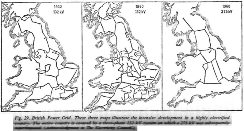
This development was embodied in the important 1926 Electricity Supply Act,
and the now well-known steel transmission towers soon began to appear. A standard
transmission voltage of 132,000 volts was adopted, and the three-phase circuits
were designed to carry 50,000 kVA on steel-coated aluminium conductors 0.77
in. in diameter, having the equivalent copper section of 0.175 sq. in. The
towers were designed for single and double three-phase circuits. In explaining
in 1927 the eight-year programme for constructing the Grid, Sir Archibald
Page said, "The Grid will go a long way towards ensuring the universal
availability of electric power throughout the country. It will bring the cost
of production in the majority of supply undertakings down to the figure which
has been attained by the few in whose areas electricity is already cheap and
abundant. [...]
The continued expansion of the grid and the increased scale on which current
is generated and distributed, has naturally had considerable influence on
the development of both transformers and switchgear. Larger and larger transformers
have been constructed. One example is the 110,000 kVA at Battersea B, first
installed for 80,000 kVA and modified for the higher output which converts
from 11,000 volts to 66,000, and has forced oil cooling. Another is the 75,000
kVA transformer at Dalmarnoch, which is air cooled, while at Barking there
are two, each of 93,750 kVA capacity. During the past few months, a British
transformer of 200,000 kVA has been supplied to the United States. Tappings
on the windings of high voltage transformers for voltage adjustment on load
have developed rapidly and are now in common use. Protection of transformers
against damage through system surges becomes increasingly important on large
networks, and this has resulted in much greater reinforcing of end turns to
withstand steep wave fronts. But possibly the most spectacular improvement
in the modern transformer is in the efficiency achieved. Values of 99 per
cent are now cmmon, and in the very large sizes 99.5 per cent is frequently
achieved. [...]
The function of opening and closing a circuit for the purpose of normal control
has usually been separated from that of opening the circuit in an emergency
brought about by short-circuit or overload. In this case, the situation has
usually been met by inserting a fusible link or cut-out in the circuit. As
loads increased, however, the two fucntions were combined in one device known
as a circuit breaker, in which a main switch was released by an electromagnetic
trip. The range of equipment thus stretches from the simple tumbler or press-button
switch with a separate simple wire fuse, to the high-voltage oil-filled or
air-blast circuit breaker in the switch yard of a large power station.
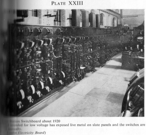
The first power stations were controlled by open knife switches on slate
or marble panel switchboards, and as currents grew in magnitude, circuit breakers
with magnetic blowouts to extinguish the arc were added. Well before 1900,
the switchboard had taken its place as a vital component of a power station,
and improvements were introduced both into the arrangement of circuits and
the design of individual switches to reduce the risk of failure and to ensure
the continuity of supply. A major modification was in the adoption of the
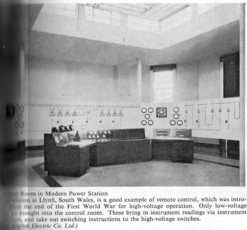
dead front, in which no live metal was accessible, a condition which became
essential on the adoption of alternating current and higher voltages. At one
stage in this development, remote mechanical control of the switches was resorted
to, the switches themselves being housed in brickwork cubicles a short distance
behind the control board. [...]
About 1940, it became evident that from a national point of view, the continued
expansion of the British grid required a still higher voltage than 132,000,
and in 1952 the Electricity Authority started on the construction of a super
grid to operate at 275,000 volts. The two main objects were to interconnect
the major groups of generating stations, and to connect new generating plant
located on the coalfields to bulk supply points in areas where there was a
deficiency of fuel. In addition, the superimposed grid would provide additional
safeguards in times of breakdown or other emergency, and so make possible
an appreciable reduction in the provision of standby plant. One line of towers
on this super grid can carry over 500,000 kW on each of two circuits, and
already a considerable part of the scheme is in operation.

[...]
The Early Telephone
[...] Early in 1877, the telephone had created a world-wide interest. Speech
had been transmitted over the existing telegraph lines, and the time had come
for commercializing hte invention. Bell offered pairs of instruments on lease
'for social purposes' at $20 a year, and 'for business purposes' at twice
this rent. Very soon the instruments were being produced in a small factory
in Boston, Massachusetts, and supplied over a wide area, including New York
and London, where Bell read a paper before the Society of Telegraph Engineers.
[...]
The idea of a central switchroom by which subscribers could be interconnected
was suggested in Octber 1877 by an enterprising journalist in Boston, and
quickly took practical shape based on the telegraph system which had already
operated to a limited extent in the United States, England, and France. At
first a ticket system enabled an operator to receive requests from individual
subscribers for a specified line between certain times, and to issue instructions
by means of a ticket to another operator, who inserted and withdrew plugs
as required.
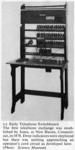
The first telephone exchange on a commercial basis was installed at New Haven,
Connecticut in January 1878. Drop indicators were used with a call bell and
two-way lever switches enabled the operator to connect his own telephone to
any line and obtain instruction. Another switch enabled him to send out a
signal in the form of a loud buzzing sound on the subscriber's receiver. A
few months later, an exchange in which cords were used was set up in Chicago.
The subscribers' indicators were arranged along a wall, and a series of horizontal
metallic rods grouped in pairs as connecting racks. These had clearing-out
drop indicators associated with them. [...]
The first telephone exchange in England was established by the Telephone
Co., Ltd., at 36 Coleman Street, E.C., in August 1879. [...]
In 1880, the instruments standardized for subscribers' use were Telephone
No. 1 and Telephone No. 2. The former, the wall type, was made of wood, having
a projecting ebonite mouthpiece on the transmitter, with a tubular receiver
and switch hook at the side, and a double magneto bell in front. The desk
type, constructed mostly of metal, carried the transmitter with its ebonite
mouthpiece on a tubular pillar with the receiver and switch hook on the side,
but the bell was accommodated in a separate wooden box. [...]
In 1896, the major trunk lines of the National Telephone Co. were purchased
by the Post Office, and at the turn of the century, common battery (CB) working
was introduced. Many inventors and many committees contributed on both sides
of the Atlantic to this important innovation. In the famous Hayes circuit,
based on a patent granted in 1892, the subscriber received current from a
large common battery locaed in the exchange and singalled by lifting his receiver
from a switch hook. [...]
When the first telephone exchanges were projected, the telegraph system with
its ramification of circuits was already established, and it was natural that
practice should follow precedent. There was, however, a basic difference in
the requirements of the two services; telegraphs were usually long-distance
circuits with lines from town to town, whereas in telephony, initially at
any rate, the main problem was to connect many subscribers in a congested
urban area with one another through a local exchange. Consequently, bare wires
strung over rooftops became the usual practice. Baldwin has given an excellent
description of the early history of overhead telephone line plant, in which
he traces the development from the practice of the telegraph engineer.
Telegraph exchanges were conveniently housed in high buildings surmounted
by a derrick from which lines radiated in all directions. The most commonly
used wire to start with was bare galvanized iron, No. 12 gauge, with other
sizes depending on the whim of the particular engineer. To prevent corrosion
in industrial towns and large cities, the wires were often protected with
an impregnated cotton covering. Although the high electrical resistance of
iron wire was a great disadvantage, it required many years of testing and
consideration before its place was taken by copper. Because of their increased
tensile strength, phosphor bronze and silicon bronze were favoured by some,
but hard-drawn copper held the field until the brittleness of bronze was overcome.
Soft copper binding wires were introduced for holding the wire to the insulator
of porcelain of various shapes, and gutta-percha covered wire was used for
leading into premises. By 1890, silicon bronze had been so much improved that
it had been brought into general use for subscribers' circuits throughout
Britain in a standard weight of 40 lb. per mile.
The congestion resulting from the large number of wires leaving the structure
over an urban telephone exchange soon called for a bunching of the circuits
into groups, and this was done by the use of multi-core aerial cables. Early
forms consisted of a number of gutta-percha insulated wires, bound together
with tape, and associated with a stranded galvanised wire to give supporting
strength. Later, rubber was substituted for gutta-percha, which cracked when
exposed to air and sunlight. This also enabled more conductors to be accomodated
in a cable of the same weight, and standard types were adopted with 26 and
52 pairs. As an example of the magnitude of the task of getting the circuits
away from an early telephone exchange, the case of Sheffield may be cited.
There, the angle iron derrick erected in 1891 accommodated over 1,000 wires.
A problem which faced the early telephone engineer was the prevention of
overhearind between circuits, when so many had to be carried in close proximity
to one another. The impracticability of the single-wire earth circuit which
had been suitable for telegraphs was soon appreciated, and in 1892, expensive
schemes of doubling, or making the circuit 'metallic' as it was called, were
carried out. Even then, induction effects were found to be serious, and twists
were introduced. The credit for this idea goes to Professor Hughes, who referred
at a dinner of the National Telephone Co. in 1895 to his paper in which he
had first announced the idea. For long-distance overhead liens, then growing
rapidly along the main roads of Britain, the system of twisting a pair between
poles and of inserting crosses, was adopted extensively. [...]
The heavy overhead long-distance lines continued to grow in number and size
until the First World War but, as even then they failed to meet the demand,
more and more cables were laid. For subscribers' lines, 1,000-pair cables
with 6 1/2 pound conductors became common. [...]
When Sir William Preece visited the Philadelphian Electrical Exhibition in
1884, the number of telephone stations in the United Kingdom was already 11,000.
He found that the comparative figure for the United States was 148,000. He
explained the discrepancy to his hosts on the grounds that in London an errand
boy cost 2s. 6d. a week, whereas a similar service in New York cost 12s. to
15s. It paid to use the telephone. Today (1960), there are still about nine
times as many telephones in the United States as there are in the United Kingdom.
[...]
Science in Telecommunication
[...] Michael Idvorsky Pupin [...] spent some time studying at Cambridge
and Berlin Universities, [then] returning to Columbia [University], where
he was appointed to a chair. It was here that during twenty-five years he
made his inventions, the most significant of which, the Pupin Coil, brought
him in $1,000,000. The patent was bought by the American Telephone and Telegraph
Co.
Thus was laid the foundation stone of 'loading' an electrical transmission
line, and the first practical application was in August 1902 when loading
coils were inserted in a ten-mile length of telephone cable between New York
and Newark, New Jersey. By this modification, the grade of transmission was
improved to that obtainable on a five-mile length of unloaded cable. [...]
In the long-distance circuits in England, open lines carried on poles had
been strengthened by increasing the size of the copper conductors. In 1895,
the limit was reached on the Longon-Leeds-Edinburgh line, when conductors
weighing 800 lb. per mile were erected. [...]
After the successful pupinization of the New York-Washington and New York-Boston
lines, the American Telephone and Telegraph Co naturally turned its attention
to transcontinental possibilities and, by loading and reinforcing overhead
lines, a New York-Denver circuit of 2,200 miles was achieved as a first stage.
On 25 January 1915, a commercial telephone service was inaugurated between
New York and San Francisco, a distance of 3,400 miles over open wires weighting
870 lb. per mile. Today the United States has a vast system comprising some
200 million miles of wire, and practically any two telephones can be interconnected
on demand. [...]
Two-wire amplified circuits were at first developed for inland trunk cables
in this country, but by 1939 had been replaced by four-wire circuits with
losses reduced to practically zero. Not only had the repeater reduced the
need for capacity correction in the line by the addition of inductance, but
carrier technique, introduced in 1920, had made it possible to transmit more
than one conversation over one pair of wires. [...]
By 1937, this new tool had made it possible to carry twelve channels on each
pair of a cable. [...]
Measurement Instruments and Standards
[...] At the International Electrical Exposition held in Paris in 1881, much
dissatisfaction with the position was expressed by practical electrical engineers,
who were still using widely 'Weber' to denote the unit of current, measuring
electrical pressure in terms of the equivalent number of Daniell cells, and
resistance in terms of miles of telegraph wire; and the new names ampere,
volt, and ohm were adopted. [...]
Professional Organizations
[...] For many years before the formation of a professional body for electrical
engineering, the pioneers who were laying the basis of the science found a
suitable forum in the Royal Society. Many fundamental communications on electrical
engineering by Sturgeon, Kelvin, Wheatstone, Hopkinson, and others have appeared
in its Transactions.
During the second half of the eighteenth century, small societies were founded
by groups of men itnerested more in the development of engineering and technology
than in pure science. The Lunar Society, so called because the meetings were
arranged at the time of full moon in order that the members could find their
way home easily, included many well-known pioneers whose names became famous
- Watt, Boulton, Murdock, Priestley, and others. [...]
In 1872, The Telegraphic Journal and Electrical Review was launched,
and continued for twenty years when, under Alabaster Gatehouse and Kempe,
it became The Electrical Review, aiming rather more at the commercial
than the academic side of electrical engineering. Later, in 1891, Lightning
appeared under the control of Robert Hammond, who also served as honorary
treasurer of the Institution for many years. One of the interesting features
of Lightning was the publication of statistics of the industry; subsequently,
under the direction of R. W. Hughman, it changed its title to The Electrical
Times and has made a considerable impact. [...]
English Social and Historical Background
[...] Soon after its introduction, the telephone assumed an important position
in the commercial world. In 1889, the trhree principal companies which had
carried through the pioneer work were amalgamated to form the National Telephone
Company, with some 28,000 lines. From 1892, the Post Office came into the
telephone field, and in 1896 all trunk lines came within official control.
The final stage in the development came in 1911, when the Post Office took
over the whole telephone system of Britain. [...]
Chronological Table
[very selected excerpts]
1837 - Cooke and Wheatstone first practical electric telegraph, on L. &
N.W. Railway, London - Camden Town
1856 - Formation of Atlantic Telegraph Company.
1871 - Society of Telegraph Engineers (later I.E.E.) founded.
1873 - Gramme first transmitted electric power over three-quarters of a mile,
at Vienna Exhibition.
1877 - Edison Electric Light Co. formed.
1880 - Society of Telegraph Engineers added 'and Electricians' to its title.
1881 - Edison constructed his first electric power station at Pearl St. N.Y.
1882 - Gaulard and Gibbs arranged transformer in series.
1882 - Tentative electric tramway at Leytonstone, London.
1882 - 35 mile 200 volt A.C. transmission at Munich.
1883 - Step down transformers come into use.
1883 - Charing Cross Electric Supply Company formed.
1889 - Formation of National Telephone Co.
1889 - General Electric Co. formed in England.
1895 - Rotary automatic telephone exchange switch introduced.
1897 - Brown invented oil-immersed circuit breaker.
1900 - Central London Railway opened.
1900 - First public 6,600 volt 3-phase supply, at Newcastle.
1905 - Niagara Falls 60,000 volt transmission over 200 miles.
1905 - First power station system control room in Great Britain at Carville.
1906 - Hewlett introduced high-voltage suspension insulator.
1920 - Emanueli introduced oil-filled cable.
1925 - Barking Power Station opened by King George V.
1929 - First section of the British 132 kV grid operating.
1929 - A.C. Multiplex 12 Channel telegraph system in operation.
1942 - British Electricity Authority planned 275 kV grid.
1946 - Central Electricity Authority connected 180 electricity compaies,
354 municipal undertakings, and 9 joint electricity authorities.
1959 - Kariba hydro-electric shceme on Zambesi, with 100 MW sets and 330
kV lines working.
1961 - Membership of Institution of Electrical Engineers exceeds 48,000.
Illustration Plates


This information comes from
- Black, Robert Monto. The History of Electric Wires and Cables.
London, England: Peter Peregrinus Ltd (in association with the Science Museum
of London). Copyright 1983. ISBN 0863410014, LOC TK3301.B564.
The 'Foreword' by John Banks states:
Industrial history, especially in its most specialised areas, does not always
get the support of the industrialist. As one of the latter and also a professional
engineer, I have an ingrained desire to keep records, but this does not ensure
that the kind of record provided in this book will result. For that we have
to rely on the enthusiasm, almost fanaticism, of the energetic story teller
which Robert Black obviously is. [...] This sustained effort has enabled him
to write a most comprehensive book, ranging from early telegraph cables to
the most recent specialised types of cables such as are required for ships
and aircraft. [...]
The 'Preface' states:
The story of the gradual evolution of electric wires and cables, from those
used in the early experiments in electrostatic telegraphy to such modern examples
as supertension power cables and optical fibre telecommunication cables, is
a fascinating one with its full share of drama and suspense. [...] In the
chapters which follow, an account is given of the development of the principal
types of electric wires and cables, from the earliest times up until about
halfway through the present century. The treatment varies in texture and cannot
claim to be comprehensive, for each cable installation is a story in itself
and availability of space has necessitated selection. Despite this and a confessed
parochial interest in two among the many great cable makers that have flourished
during the period (Callendars and the B.I. Company, by whose decendant BICC
I have been employed for nearly forty years), it is hoped that the reader
will share in the fascination and pleasure that building up a cable collection
and compiling its history has brought. [...] It was Jim Temple Hazell who
first encouraged my interest in the subject, and helped the start of a collection
of cables by passing over the duplicate samples from the Hunter-Hazell Collection,
now in the Science Museum. [...] The author's thanks are due to Mr. John Banks,
Managing Director Group Services, BICC plc., President of the Institution
of Electrical Engineers, for permission to proceed with the writing of this
history and for providing a Foreword, to his colleagues at Wood Lane for encouragement
and advice, and particularly to his fellow library staff, who have suffered
from a plethora of cable samples and documents without complaint for a long
while. [...]
The 'Acknowledgements' states:
Diagrams and photographs are reproduced by kind permission of the following:
Ferranti Limited (3.2)
Pirelli General Cable Works Limited (9.1)
British Patent Specificication No. 933 of 1851 (5.1)
US Patent Specification 304/539 of 1884 (5.2)
All others, unless otherwise stated, by permission of BICC plc.
The following information is excerpted from this book.
Early Telegraph Cables
In the early years of the eighteenth century, many natural philosophers experimented
with electricity, with a view to establishing its applications. Among these
was one Stephen Gray, F.R.S., described as a Charterhouse Pensioner, who demonstrated
the principles of conduction and insulation in 1730 by suspending a damp hempen
line on silk threads. He found that he was able to transmit electrostatic
charges for distances of up to several hundred feet. When metallic wire was
substituted for the damp hempen cord, the charge could be carried over circuits
several miles long.
Six years later, John Woods improved on the system, and in 1747, Sir William
Watson, F.R.S. constructed a two-mile line with an earth return. This circuit
was set up in the July of that year, and was routed across the River Thames
by way of the old Westminster Bridge. In order to demonstrate the effectiveness
of the circuit, Sir William completed it through the body of an assistant,
who held the far end of the wire in one hand, and with the other touched the
water with a metal rod. It was reported that his reaction to the static discharge
from a Leyden Jar "completely vindicated the result which had been anticipated".
An interesting development and the first recorded account of the use of paper
as an electrical insulating material, was given in a paper presented by Don
Francisco Salva (1751-1828) to the Academy of Science in Barcelona in December
1795. In describing his experiments in telegraphy to the Academy, he also
suggested the possibility of underground transmission by cable:
"...it appears, little short of impossible to erect and maintain so
many wires" (with the electrostatic telegraph system that he was contemplating,
Salva would require 22 wires, one for each of the 22 letters of the telegraph
alphabet) "for even with the loftiest and most inaccessible supports,
boys will manage to injure them, but as it is not necessary to keep them very
far apart, they can be rolled together in one strong cable, and placed at
a great height. In the first trials made with a cable of this kind, I covered
each wire with paper, coated with pitch or some other ideoelectric substance,
then tying them together, I bound the whole with more paper, which eventually
prevented any lateral escape of the electricity. In practice, the wire cable
could be laid in subterranean tubes, which for greater insulation, should
be covered with one or two coats of resin."
This grand concept resulted in the laying down of a 26-mile long telegraph
line between Madrid and Aranjuex. By means of electrostatic charges, Don Salva
managed to transmit effective signals over it. Any underground section would
no doubt be out of sight, if not out of reach, of the boys! [...]
Francis Ronalds had set up an eight-mile telegraph circuit in the garden
of his home in Hammersmith, now known as Kelmscott House in the Uppoer Mall.
The telegraph was described in some detail in a small book, published in 1823
and entitled Description of an Electric Telegraph and of some other Electrical
Apparatus. From this it is clear that Ronalds' main interest was to establish
whether the electric fluid in its static form could be made to travel over
long distances without undue delay. For this purpose, he set up two wooden
frames twenty yards apart, between which he strung wire backwards and forwards
to form a continuous length of just under eight miles. THe wire passed through
loops of silk at each of the 37 hooks on the 19 bars on the two frames. The
two ends of the wire were attached to pith ball electrometers. "When
the line was charged by connection to a Leyden jar, the electrometers at the
near and far ends diverged at exactly the same moment, and on discharge by
being touched by the hand, collapsed simultaneously." [...]
[William] Cooke made contact with the Directors of the Company [of the London
and Birmingham Railway] and with their engineer Robert Stephenson, initially
with the object of interesting them in a fire alarm system based upon his
mechanical telegraph and an alarm bell, which he demonstrated to them on 4th
July, 1837. They were, however, interested in a means of signalling between
Euston and Camden Town, with the object of informing the men operating the
winding engine when the train was ready to start.
A further demonstration was arranged for the 9th July, when message sending
over a distance was demonstrated to Robert Stephenson and to Robert Creed,
the Company Secretary. For this second experiment, Wheatstone had set up a
"hastily made telegraph" employing four needles and four wires.
The onlookers were impressed, and expressed the wish for the system to be
demonstrated over a still greater distance. Accordingly, an extended line
was prepared [by Charles Wheatstone] over the route from Euston to Camden
Town.
It is known that the installation of telegraph wires over this route included
a section at least of the second of the conductor systems described in the
patent of 1837: "The long extensions of conducting wires, which may be
called telegraph wires, may be lodged in channels formed in wood rails and
lines with any suitable resinous matter, with a covering rail of wood over
the channels to protect the wires from injury and from damp.... Another form
of rail containing distinct channels for the several wires, each of which
channels is closed by a fillet of wood driven into it. Such rails may be laid
underground when that is more convenient than to place them above ground on
posts, and some parts of a long line may be under ground and other parts above
ground, and extend along the sides of public roads or railways or otherwise,
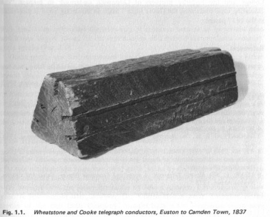
as is most convenient and suitable to go from one terminus to the other."
As depicted in the patent, the five copper wires were laid in long wooden
baulks of trapezoidal cross section, the grooves being plugged with wooden
strips and the baulk finally painted with a preservative tar compound (Fig.
1.1). The buried section of the line, in the form of these baulks, was laid
in a trench alongside the railway track. The trench was filled in with pitch.
The length of the section so buried was just under two miles. [...]

The telegraph was a success. The wood baulk conductor array functioned satisfactorily,
despite the fact as may be seen in the lengths that have survived, that the
conductors used were not insulated in any specific way other than by the timber
and its preservative tar compund. In the original specification, it was suggested
that, if necessary, the wires could be covered with thread and varnished.
[...]
The Grosvenor Gallery and Deptford
In retrospect, the year 1871 was an important one for the electric cable
industry, if such it could be called at that time, bearing in mind its preoccupation
with telegraph cables, for it was in this year that Zénobe Gramme (1826-1901)
perfected the ring dynamo and a really satisfactory source of electric power
became available. [...] The use of arc lamps spread rapidly, particularly
with the development of the improved version of the lamp by Paul Jablochkoff.
In 1878, these improved lamps, known as Jablochkoff Candles, were used in
London for the lightning of the West India Dock, Billingsgate Market, Holborn
Viaduct, and parts of the Thames Embankment.
In general, very little is known of the type of cable employed in these installations.
Often, earth returns were used in conjunction with a plain copper wire supported
on some form of insulator. [...]
It was not until 1911 that a really tough outer sheath was developed for
application to rubber cables. This was done by the St. Helens Cable and Rubber
Company of Warrington, who, in addition to their cable making activities,
had been manufacturing solid rubber tyring by an extrusion process, for the
wheels of horse-drawn vehicles, particularly Hansom cabs. From this was derived
the term 'cab-tyre' sheathing. Designed to be "of great mechanical strength,
water and corrosion proof, flexible, smooth, and 'un-kinkable' ", it
was ideally suited for the protective sheathing of cables for such arduous
duties as might be experienced in collieries.
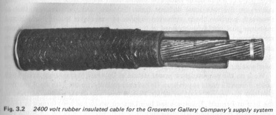
In 1886, the India Rubber and Gutta Percha Company produced a cable consisting
of a 19/15 gauge tinned copper conductor, insulated with 0.21 in. of pure
and vulcanized India rubber, with a double jute braiding as an outer covering.
The cable was designed to operate at 2400 volts single phase a.c. This cable
was to be used in the now famous Grosvenor Gallery installation. [...]
It all began with the Paris Exhibition of 1882, at which the newly exploited
electric light played an important part among the exhibits. The Earl of Crawford,
one of the Commissioners appointed by the British Government to visit the
Exhibition and report back on the latest developments, on his return suggested
to Sir Coutts Lindsay, who was the proprietor of the fashionable Grosvenor
Art Gallery in Bond Street, that he should install electric light in the Gallery.
Sir Coutts agreed, and in early 1883 a pair of Marshall's semi-portable engines
were erected in an out-building behind the Gallery. These were belted to a
couple of separately excited Seimen's alternators, generating single phase
current at 2000 volts. The plant supplied arc lights in series, and an automatic
regulator kept the line current constant at 10 amperes. [...]
Interest in the plant soon spread among the local shopkeepers and residents,
and requests for supplies of electricity were met initially by installing
individual transformers, or secondary generators as they were then called,
in the house of each consumer. The primaries of all the transformers were
connected in series with the line, in accordance with the system then recently
introduced by Gaulard and Gibbs. The high tension current was transmitted
by overhead cables supported from poles on the house tops. This overhead system
had the advantage that despite the restrictive provisions of the 1882 Electric
Lighting Act, nothing was involved in obtaining permission for the installation
than the consent of the house-holders and of the vestries concerned. [...]
The result of all this was that the small installation very soon became seriously
overloaded. It was decided therefore to establish a permanent generating station
under the Gallery, and on a considerably larger scale. The necessary construction
work commenced on December 1884. [...]
Sir Coutts Lindsay then joined the Earl of Crawford and Lord Wantage in forming
a small private company, to be called Sir Coutts Lindsay and Company Limited,
but which was more famously known as the 'Grosvenor Gallery Electric Lighting
Works' or as 'The Grosvenor Gallery Company'.
The new station went into service towards the end of 1885. [...] From the
start, a great deal of trouble was experienced, and indeed the installation
proved practically unworkable. Numerous complaints were received, arising
from poor regulation, loss of supply, overloading, and breakdowns, until the
situation fast was becoming desperate. [...]
On the 13th January, 1886, the Directors appointed [Samuel] de Ferranti [as]
Chief Engineer of the Company, to be in full charge of the station. In the
space of a few months, Ferranti managed to carry out a complete overhaul of
the system. The overhead network was re-modelled for parallel working, transformers
to his own design were installed in place of the Gaulard and Gibbs series
devices, the voltage was increased to 2400 volts by connecting the windings
of the Siemen's alternators in series instead of in parallel (each alternator
had two sets of 1200 volt windings), and new switchgear was designed and erected.
The vulcanized India rubber cable used for the overhead supply network was
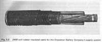
that supplied by the India Rubber and Gutta Percha Company (Fig. 3.2), and
was suspended by leather thongs from a steel catenary wire which ran between
suitable iron masts erected on convenient roof tops and a lattice tower on
the roof of the Gallery itself. Two cables, spaced 12 inches apart, were used
in each connection, being shackled off at the masts. The cable was supported
in Johnson and Phillip's 'fluid type insulators'. By 1888, the system had
grown to the extent that some four hundred premises were being supplied with
electricity.
[...] So successful were the new arrangements, that customers who had been
infuriated by the repeated breakdowns which had occurred with the earlier
system, had their confidence restored, and the demand for new installations
increased rapidly. The Directors decided to form a new company to take over
the station, and to extend operations in accordance with some ambitious plans
that had been proposed by their Chief Engineer. These were concerned with
the setting up of a remote generating station to supply electricity to London
on a really large scale. The new company, The London Electric Supply Corporation
Limited, was registered on 26th August 1887, with an authorized capital of
£1,000,000 in shares of £5 each, of which over half was subscribed.
Sebastian de Ferranti was appointed Engineer and Electrician to the new company.
[...]
This wide area [along the whole north side of the Thames] was to be supplied
with electricity from a generating station located at Deptford on the South
Bank of the River Thames, about eight miles from the heart of London. The
output of the station was to be such that it would be capable of supplying
current for the electric lighting of the whole area at an unprecedented a.c.
transmission voltage of 10,000 volts. The location of the generating station
on the river, some distance from the town, had the advantage that at Deptford,
land was cheap, unlimited supplies of water were readily available, and sea-borne
coal could be obtained at low prices. There would be no noise from moving
machinery to disturb the slumbers of local residents, and no traffic congestion
occasioned by the carriage of coal through the streets to fuel the power station
boilers. For a parish of 200,000 lights, it was estimated that the fuel requirements
would necessitate the passage of some 200 cart-loads of coal each day.
Work on the proposed new power station at Deptford began during April 1888,
under Ferranti's direct supervision. [...]
The erection of the station was rapid, and in October 1888, the press were
invited down to view the progress made. [...]
The Electrical Engineer of 27th October 1888, commented: "On
Wednesday, the designer of the great Deptford installation was laughingly
dubbed the Michael Angelo of that installation, because from first to last,
from foundation to top of highest turret, architecture, materials, foundations,
and machines, all were specified or designed by one man, and the credit of
the success of the really first central station in England will have to be
given, without detracting one iota in favour of any other person, to Ferranti...
It required not only courage on the part of the engineer, but also a degree
of confidence that few men possess in earlier days of industrial development."
At the same time that work commenced on the building of the station, consideration
was given to the problem of transmitting power to the capital. Arrangements
were made with the railway companies (the London and Brighton; the London,
Chatham, and Dover; the Metropolitan; and the South Eastern) for permission
to carry the trunk mains along the parapets and bridges of the railways to
the distribution sub-stations in London. Six mains, or conductors, were to
be provided, two of which would be brought to Cannon Street, two to Blackfriars
Bridge, and two to Charing Cross. The use of railway property offered considerable
saving, in that it precluded an approach to each parish and vestry for permission
to excavate their roadways. [...]
Originally it was intended to transmit the power from Deptford to the Grosvenor
Gallery by means of jute insulated cables made by the Fowler Waring Company.
This was entirely satisfactory from an electrical point of view, but suffered
from the disadvantage that its inflammable nature, in close proximity to passing
steam locomotives, gave it a tendency to catch fire. Ferranti therefore decided
to use a type of mains that he had specified in his patent application of
1885.
This patent specification had described a complete distribution system for
electric lighting. Current from the generating station was to be transformed,
or converted as he termed it, down from the supply voltage to 100 volts for
supply to customers. The specification also details the type of mains to be
employed for the distribution:
"The mains for conveying the current I form of concentric tubes drawn
one over the other with insulating material between them."
The insulating material proposed was to be paper saturated with shellac in
solution. [...]
The proposal to make this simple concentric design of tubular main did not,
however, meet with Post Office approval. In a paper read before the Institution
of Electrical Engineers in 1889, W. H. Preece, the Chief Engineer to the Post
Office, said:
"It is quite certain that if a single conductor between Deptford and
London were subject to rapid alterations under a potential difference of 10,000
volts, the current returning by way of the earth, every telephone circuit
in the metropolis would be disturbed, and probably rendered unworkable."
Preece carried out a series of experiments with a lead sheathed concentric
cable, and found that when he used the sheath as a return for a.c. at a frequency
of 80 cycles/second, near the frequency of a Ferranti alternator, interference
in an adjacent telephone line resulted. When, however, he used the outer conductor
as the return, all was well. He came to the conclusion that an earthed sheath
placed over the concentric main reduced the electrical interference to negligable
proportions. Ferranti acted upon this information, and the following, well
known, construction of the Ferranti main resulted (Fig. 3.3).
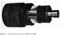
A copper tube, 13/16 inch diameter and 20 ft long, was insualted with wax-impregnated
paper rolled on spirally, from sheets 20 ft in length and about 36 in. wide,
either by hand, or later by special machines which avoided straining the paper.
The sheets of paper were overlapped during application, until 0.5 in. of insulation
had been applied. THe outer conductor, of the same cross-sectional area as
the inner one, and 31/16 in. in diameter, was slipped over the insulated inner
conductor, and the combined assembly was drawn through a die in a heavy tube
drawbench, to compact the outer conductor down on to the paper insualtion.
A further 3/32 in. of waxed paper was then rolled on to the outer conductor,
and the whole enclosed in a thin iron tube of 2 3/8 in. diameter. The iron
pipe had a braised seam, and the space between the paper and the iron was
filled with hot bitumenous compound from a central injection point.
The jointing technique developed for these mains was of considerable importance.
Of necessity, joints had to be simple, as in the four seven-mile mains laid
between Deptford and the West End, there would have to be over 7000 of them.
It is believed that Ferranti got the idea for the joints (Fig. 3.4) from the
old wooden water mains, some of which are presevered in the Guildhall Museum,
and which consisted of logs with a male cone at one end which was fitted into
a female cone in the end of the next log, which in turn had a male cone at
its other end.
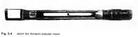
[...] Before bringing the ends of the main together, an iron sleeve was slipepd
over one length. This sleeve was so shaped as nearly to fit the protective
iron pipe, but elsewhere was somewhat larger in diameter, and in the enlarged
part a sleeve of prepared paper was placed. When the jointing of the outer
conductor was complete, it was wrapped with the prepared paper to bring the
diameter up to that of the iron pipe, the sleeve was moved into position,
and hot wax was forced in through a hole in the sleeve to displace air and
to fill up any spaces not occupied by the prepared paper. The ends of the
sleeve were fixed down to the protective pipe by corruguations applied by
a tool, and the hole through which the wax was introduced was closed by a
screw plug.
There was, of course, considerable criticism of the use of a voltage as high
as 10,000 votls with these mains, and doubts were cast upon their safety in
the event of a fault. Ferranti devised a demonstration to alleviate the doubts
and to convince even the most skeptical of their safety. Before a large number
of witnesses, Harold Kolle, Ferranti's personal assistant, held an un-insulated
cold chisel to the live main with his bare hands, while a colleague with a
slege hammer drove it through both conductors. As the chisel cut through the
main, the main fuse link cut off the supply without damage to the equipment
or injury to the very brave man involved. There is an apocryphal story that
Kolle, asked later if he had not been frightened, replied "Frightened?
I was scared out of my life. Young Henry had never used a sledge hammer before!".
[...]
Originally, it was intended to install twelve 10,000 horse-power generating
units, but the complete plans were partially forestalled by the operation
of the Electric Lighting Act of 1882, and the subsequent Board of Trade Enquiry
held in 1889. These, in effect, split up the area which was to have been supplied
from Deptford among a number of smaller companies.
On top of all this, the scheme was beset with a number of disconcerting and
almost disastrous incidents. One of the jointers was killed by a passing train
during the installation of the mains along the railway embankment. On another
occasion, one Joseph Selway was killed in the explosion at Stowage Wharf (the
site of the power station) on 9th April 1890. The accident occurred while
the works were being inspected by Major Marindin, who headed the Board of
Trade Enquiry; a steam pipe on one of the engines burst, and Selway was blown
28 ft by the explosion, and three other men were seriously injured.
A devastating fire occurred at the Grosvenor Gallery while it was being used
as a temporary sub-station. A power arc occurred during switching, which set
fire to the wooden roof before it could be extinguished. This resulted in
the complete destruction of the sub-station, and the loss of supply from the
15th November 1890, when the fire took place, until the following February.
During this period, a number of customers were lost, and there was no income,
only considerable expenditure. The opportunity was taken to push ahead with
what Ferranti referred to as "the permanent work" to an extent which
could not otherwise have been possible. The whole system of overhead lines
radiating from the Grosvenor Gallery were removed, and replaced by underground
cables.
The Board of the Electric Supply Corporation were not, however, very happy
with these misfortunes. They had lost a large amount of money, and as the
prospects of obtaining the virtual monopoly of the electricity supply for
London began to fade, sodid their confidence in their Chief Engineer. At the
meeting of the shareholders in March 1892, it was announced that during the
year, "the engagement of Mr. de Ferranti has ceased by the effluxion
of time".
Although this must have been a severe blow to Ferranti, particularly as he
had been accused by one member of the Board as being "sadly lacking in
prevision", he was now free to transfer elsewhere his experience, his
valuable patents, and his unrivalled knowledge of high voltage technique.
He did not have long to wait. The Directors of the newly formed British Insulated
Wire Company, having taken the opinion of Mr. W. H. Preece as to the value
of the Ferranti patents relating to electric cables, offered him a seat on
their board, acquired his patents, and insured his life for the sum of £20,000.
In retrospect, Deptford was a magnificent and daring enterprise. [...]
In the opinion of Colonel Crompton, "electricity supply owes far more
to Ferranti than to any other man. All the substantial features of supply
are founded on his work at the Grosvenor Gallery and at Deptford".
Electric Lighting Cables
[...] The view has been expressed that had the business of electricity supply
been destined to continue on the same limited scale as that of the earlier
undertakings, there is little doubt that the direct current system would have
been generally adopted.
One of the protagonists of the low voltage d.c. system was Thomas Alva Edison
(1847-1931), an inventor with Joseph Wilson Swan of the incandescent filament
lamp. Edison was very much aware of the dangers of high voltage electricity,
as at that time he was in his laboratory at Menlo Park, New Jersey, with other
workers in the field, considering the use of electricity in judicial execution.
During those years, the electrical press contained many references to this
work, as well as to the development of a 'secret death ray' which was reported
to have been applied to a flock of sheep with dire effect. The journals also
record the prolonged debate as a result of which the term 'electrocution'
entered the language, being thought a suitable word to describe the particular
electric shock treatment finally decided upon.
Edison, in a manner not unlike that of Ferranti around the same time, worked
out the details of a complete system for the distribution of electricity at
low voltage to customers. One problem encountered with low voltages was that
of 'copper loss' - the reduction of the supply voltage with the distance of
the customer from the generating station. As Edison determined to supply his
customers at 100 volts, it is said that he generated at 110 volts to ensure
the full voltage reaching the customer. The practice of an additional ten
percent has survived to the present day even though it is no longer necessary,
and is found in the voltage series of 11 kV, 22 kV, 33 kV, 66 kV, 132 kV,
etc. [...]
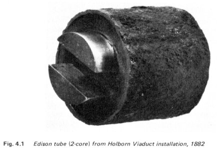
The mains which he proposed for the commercial distribution of electricity
were [...] to consist of two large segmental shaped copper rods (Fig. 4.1),
separated from each other by thick cardboard spacers strung together on a
jute string and contained in an iron pipe with a screw thread at each end.
This pipe was 20 ft in length and was subsequently filled with a bitumen compound
by means of a hand operated suction pump. These rigid mains were to be known
as 'Edison Tubes', and in a similar manner to the Ferranti mains detailed
a year or so later, and which only reached the stage of commercial application
in 1889, were of such a length that they could be transported around the average
street corner on a horse-drawn cart.
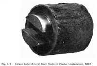
[...] The installation was started in January 1882, and a central generating
station erected in the basement of No. 57, Holburn Viaduct, the London offices
of the Edison Company. Mains in the form of Edison tubes were laid in subways
under the Viaduct to supply the street lights from Newgate Street to Holborn
Circuit, and numerous buildings along that route. [...]
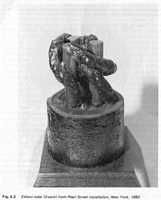
In 1883, Edison adopted the three-wire d.c. system which had been introduced
[in] England in the previous year by Dr. John Hopkinson in Patent No. 3576
of 1882. [...]
In adopting the three-wire system, Edison had to modify the arrangement of
the conductors in his tube. These now took the form of three solid rods of
copper of the same circular cross-section, individually lapped with jute cord
in a very open lay (Fig. 4.2). Three such lapped conductors were then bound
together in trefoil formation by means of a fourth cord and the whole slipped
into the iron pipe. The bitumen compound was introduced as before. Special
joints were again designed to overcome expansion, to introduce right-angle
bends and to enable service cables to be connected.
[...]
Paper Insulated Cables
[...] Towards the end of 1892, a horizontal engine was acquired [by the British
Insulated Wire Company (B. I. Co.) ] from St. Helens, where it had been used
to grind pills. It was set to drive a Brush arc lighting machine. This was
to supply sixteen arc lamps mounted on special lamp standards, which were
erected chiefly at important corners of the town [Prescot]. These arc lamps
were in addition to the twenty 16-candle power incandescent filament lamps
which had been mounted in converted gas standards.
The engine and arc lighting machine were appropriately and inevitably named
"Joan of Arc", and were said to be a good deal more reliable than
either the circuits or the lamps which they supplied. It is recorded that
a man was appointed to go round the town after lighting-up time each night,
and to apply a vigorous kick to the base of any arc lamp standard in the event
of the lamp 'sticking'. [...]
In March 1892, all the four 10,000 volt Deptford mains were put out of commission
simultaneously by a fire which broke out in material stored beneath the arches
of the South Eastern Railway Company's viaduct near Spa Road, Bermondsey.
Despite the fact that the mains were carried along the parapet of the viaduct,
the fire was so intense that the exposed section of the mains was completely
destroyed. To prevent any similar accidents in the future, it was decided
to put this section of the mains underground.
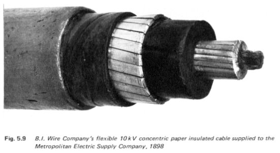
By virtue of Sebastian Ferranti's influence with the London Electric Supply
Corporation, an order was placed with the B.I. Wire Company for the supply
of two 30-yard experimental lengths of 11,000 volt flexible, paper-insulated
concentric cable. These cables, when made, were the first flexible paper-insulated
cables to be employed at this voltage anywhere in the world. Their construction
followed the now familiar B.I. pattern; the inner conductors were made up
of 7/0.064 in. diameter wires, giving a nominal cross-sectional area of 0.0225
sq. in. The outer conductor in one case was formed of round wires, and in
the other of flat strips. The experimental cables were put into service in
the late spring of 1893, being used to connect a temporary testing station
into the existing Deptford Main.
The lengths of experimental cable proved satisfactory, and a further order
for 15 miles of 0.25 sq. in. concentric cable, to the London Electric Supply
Corporation's own specification, was received in 1896 (Fig. 5.8).
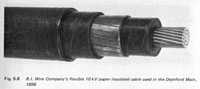
Two years late[r], in 1898, a 42-mile length of 10 kV flexible concentric
cable, with 0.54 sq. in. conductors and capable of carrying 7.5 MVA per phase,
was supplied to the Metropolitan Electric Supply Company. This differed from
previous cables in that it possessed a segmental inner conductor built up
over a rope core (Fig. 5.9).
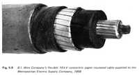
In the last years of the century, some seven miles of three-core, 5000 volt
cable was supplied to the Notting Electric Lighting Company and to the Kensington
and Knightsbridge Electric Lighting Company. This was to carry power from
their new, jointly owned power station at Wood Lane, Hammersmith to the surrounding
area. The Wood Lane Power Station started operation in October 1900, and is
of historical importance because it provides the earliest example of high
voltage three-phase generation and transmission in this country. It is now
part of the laboratories of BICC Research and Engineering Limited. [...]
Three-Phase Cables
[...] It was in 1883 that Tesla constructed his first commutator-less motor.
In the following year, he emigrated to the United States and in due course
became an American Citizen by naturalization. In 1887, he formed the Tesla
Electric Light Company and was free to develop into a commercial form many
of his earlier ideas. In addition to the discovery of the rotating field in
motors, Tesla introduced the use of polyphase systems of alternating current
and invented the induction motor.
Following Tesla's pioneer work, polyphase transmission was introduced into
North America by the General Electric Company in 1893. Three-phase current
was used for the lighting of the Chicago World's Fair which took place in
that year. This was not, however, the first application of a polyphase system.
Pride of place must go to the overhead transmission line from Lauffen to Frankfurt,
a distance of over 100 miles, in connection with the lighting of the 1891
Frankfurt Exposition. The circuit operated at a voltage of 30 kV. [...] Other
early examples of three-phase transmission were the Niagara project in 1895,
and its adoption by the Kensington and Notting Hill Electric Lighting Companies
in 1899.
For three-phase transmission by cable, a three-core construction was desirable.
In the early days of single phase alternating systems, the concentric structure
was adopted by the B.I. Wire Company as eminently suitable, and was derived
from the Hopkinson 3-wire d.c. system. But the logical extension to a triple
concentric for three-phase currents, though producing an aesthetically attractive
design of cable, gave rise to a considerable loss in flexibility. This was
not the case with a multi-core cable in which the separate cores were cabled
together, the spaces between the cores (if circular cores were used) filled
with additional jute or paper fillers, and the assembly held together with
a paper belt of sufficient thickness to provide additional insulation between
the cores and the sheath.
The 'clover leaf' cable in which shaped cores replaced the round ones was
a substantially improved design introduced by the B.I. Wire Company under
the influence of the Ferranti patents. It enabled the dimension of the cable
to be reduced for a given cross-sectional area of conductor and given supply
voltage. [...]
An early example of this 'clover leaf' design was the three-core 5.25 kV
paper insulated cable supplied for Wood Lane Power Sation in Hammersmith (Fig.
6.1) [...] which was the first in this country to generate a three-phase supply.

[...] At some time between 1900 and 1902, the Montreal Light, Heat, and Power
Company installed a three to four mile length of three-core paper insulated
cable on their Chambly circuits. The cables were commissioned in 1902 at 25,000
volts with a grounded neutral, and were still in service in 1949. The cable
was made by the National Conduit and Cable Company of New Jersey, who had
acquired the Norwich Insulated Wire Company in 1891. The National Conduit
and Cable Company later became the present Anaconda Wire and Cable Company.
[...]
The Thury Continuous Current System
Despite the fact that by the year 1900, high voltage alternating current
transmisson and distribution was firmly established and three-phase distribution
was being adopted in the United States, in Europe, and in the United Kingdom
on an ever-increasing scale, there was still interest in the high voltage
direct or continuous current system. This has been pioneered by Professor
Thury on the Continent since the first installation, under his direction,
in Italy in 1889 by the Society Acquedotto de Ferrari-Gallieri. This initial
installation comprised a 75 mile circuit capable of transmitting some 630
kW at a 'pressure' of 14,000 volts. The introduction of high voltage d.c.
as opposed to low voltage d.c., supported by Edison and others slightly earlier
in the era, was to culminate in the Moutiers-Lyon System, erected in 1906.
In a paper presented before the Institution of Electrical Engineers in March
1907, J. S. Highfield, then a member of the Council and later to become President,
gave a comprehensive account of the Thury System and compared it with the
corresponding three-phase a.c. system. From the results of many tests, he
concluded that a direct current pressure of at least twice as great as an
alternating current pressure may be used on the same overhead line insulators
and on the same underground cable. The direct current system worked on the
equivalent of a three-wire system, the middle point of the system being connected
to earth so that one line was operating at a pressure above earth and the
other at a pressure below. In this way, and using the same insulation, the
effective direct current pressure could be doubled. [...]
Protective Systems and Limitations of Solid Type Cables
[...] Solid type cables with screened cores proved eminently satisfactory
at 33 kV, and were used, despite the fact that they were very much more expensive
than overhead lines, to run power transmission systems underground in the
vicinityof large towns. As the demands upon the supply system increased, higher
and higher transmission voltages were adopted. With overhead lines, no serious
problems were introduced, but with underground cables the use of voltages
of the order of from 40 to 60 kV imposed a severe strain upon them. A strain
for which they were not designed. Another limitation was the fact that cables,
by virtue of their large capacitance, took the full force of any voltage surges
induced in the overhead by lightning, and the resulting induced over-voltages
resulted in frequent breakdowns. [...]
Telephone Cables
Following the invention of the telephone by Alexander Graham Bell, who patented
his invention in 1876, the first telephone company in the United Kingdom was
formed in 1878. This was registered on the 14th June as the Telephone Company
Limited (Bell's Patents). The choice of telephone cables was initially limited
to the already available gutta percha insulated wires which had been used
so successfully for telegraph purposes from about 1848 onwards, but while
gutta percha possessed good insulating properties, particularly under moist
conditions, the dielectric constant of the material, 4.43, resulting in some
distortion of the speech waveform, and in consequence, bare wires supported
on insulators from poles were found to be superior. A speech-carrying wave
is the resultant of the simultaneous transmission of a great many intermittent
trains of waves of frequencies varying from about 50 Hz to 3000 Hz. Because
of the complexity of the waveform, any considerable length of gutta percha
insulated wire in the circuit would mutilate and distort it to such an extent
that the reproduction of intelligible speech would be prevented. Short lengths
of such insulated wire could be used where underground transmission was essential.
[...]
As mentioned above, the use of telegraph cables for telephony could only
be regarded as expident in cases where undergrounding was imperative. The
distortion of speech due to the high permittivity of the dielectric could
be overcome by the use of bare wires and, in consequence, the early growth
of the telephone service in this country was provided for almost exclusively
by the use of overhead wires, and this, together with the early electric light
distribution system which was similarly disposed, did nothing to enhance the
skyline in the larger towns and cities. This was not only the situation in
the United Kingdom; in America also, overhead wiring was a problem, as is
evidenced by the contribution of W. H. Preece (later Sir William Preece) to
a discussion on Underground wires, the subject of a paper presented by W.
M. Callender in America in 1884.
Mr. Preece observed: "When I was here, seven years ago, I saw your corporation
spending heaps of money in beautifying your streets and in the erection of
beautiful buildings, and then allowing them to be disfigured with those hideous
posts overhead with wires strung on them. The only advantage that I have yet
observed with those overhead wires has been that in hot weather in some pace
they form very convenient shade. Beyond that I know of no earthly reason why
they should be put up." [...]
With the emergence of the dry core telephone cable (Fig. 14.3), there was
very little change in the design of telephone cables for many years. Problems
there were with the exclusion of moisture from the cores, and this was achieved
by lead sheathing, with the design of satisfactory terminations and with the
prevention of the phenomenon of cross-talk.
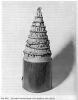
[...] It was soon realised that the transmission qualities of a cable could
be improved consideraby by one or both of two methods: by introducing an inductance
in series with the line, or by amplifying the signals (attenuated electromagnetic
waves) at intervals along the cable. These two techniques are more generally
referred to as 'loading' and as 'repeaters'. [...]
Initially, the carrier current system could only be used with opern wire
telephone lines, since the air insulation enabled the carrying of very high
frequencies. With the development of low permittivity insulation employing
polystyrene or polyethylene spacers within a metallic tube, it was not long
before the transmission of large blocks of tleephone traffic over multi-core
coaxial cable become the established practice. The technique ensured the viability
of the submarine telephone cable, which would otherwise have been uneconomic
unless a large number of channels could be provided on a single coaxial cable
(Fig. 14.4).
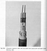
[...]
Colliery Cables
In a modern colliery, a very wide range of electric cables are employed,
for power supply in the shafts and roadways, as trailing cables for coal cutters,
as pliable armoured conveyor cables, as drill cables, remote control cables,
cables for the various electronic systems employed for monitoring, signalling,
and telecommunications, as shot firing cables, and as specially flexible cords
for the electricity supply to the lamps on miners' caps.
The conditions to which this range of cables can be exposed may be arduous,
and in consquence the cables must possess very special properties, which include
fire resistance, weather and water resistance, toughness to withstand contact
with rough and abrasive objects, and in addition, considerable flexibility.
The installation of long vertical lengths also determines certain of the cable
characteristics. For example, oil-impregnated paper cables had to be designed
with non-draining impregnating compounds in order to preclude undue ionization
as the cable drained under electrical load and gravity.
Above all, electrical installations underground had to be so designed that
they were flameproof, and any ignition of the explosive gases which might
seep into the mine workings, by sparks or arcs occurring during switching
or coupling of cables, had to be precluded or rendered harmless.
It is generally held that electricity was first used to displace pit ponies
from their underground haulage activities at the time when Callenders' vulcanized
bitumen insulated cables were introduced in a pioneer colliery electrification
scheme, at Abercanaid near Merthry Tydfil in 1891. Early VB insulated cables
had stranded copper conductors and were finished by being taped or braided,
but for colliery work, double rope armouring was introduced at an early date
to give protection without impairing the flexibility of the cable. [...]
PVC insulated power cables were offered by the manufacturers for operation
at voltages up to 3.3 kV.
By 1969, catalogues of Mining Cables were giving details of power cables
with stranded copper or solid aluminium conductors, with extruded PVC insulation
in conformity with a British Standard. The cable cores were identified by
colour coding: two-core cable, having red and black coloured cores; three-core,
[having] red, yellow, and blue; and four-core, [having] red, yellow, blue,
and black. [...]
The principal characteristics required of trailing cables are those of flexibility
and resistance to abrasion. More recently, fire resistance has also assumed
an important role. From the earliest days of colliery cables, vulcanized rubber
proved to be the ideal insulation, both electrically and mechanically. With
the development of the tough cabtyre sheathed cable, and the practicality
of incorporating flexible steel wire armouring, there has been little change
in the design of the various types of trailing cables over the years.
Coal cutter cables
Coal cutter cables normally possessed three or five cores, and operated
at 660 volts. The cores were colour coded: red, white, and blue, together
with in the five-core cable, green for earth and black for a pilot core.
The cores were laid, very much after the manner adopted with the old vulcanized
bitumen cables, in a specially shaped centre filler or cradle, and enclosed
in an inner sheath, ribbed internally to fill the interstices between the
cores. Over this inner sheath could be applied a screen of tinned copper
wires (applied spirally), followed by an outer sheath of fire-resisting
polychloroprene compound. This construction was known as the collectively
screened design, an alternative to which was the individual screening of
the separate cores.
Pliable armoured conveyor cables
The construction of the conveyor cables was similar to that of the coal
cutter cables, save that the collective screen was replaced with a pliable
armour of galvanized steel strands applied spirally, and the cable was sheathed
overall with a fire-resisting polychloroprene compound. Multi-core cables
with three, four, and five cores were usual.
Drill cables
Drill cables normally operated at 250 volts, and were similar in construction
to smaller versions of unscreened coal cutter cables. The cores were insulated
with vulcanized rubber and, again, the sheath was of polycholoroprene. To
achieve additional flexibility, the cores in their cradle could be assembled
with a short lay.
Remote control cables
These small cables were two and three core versions of pliable armoured
trailing cables, and were intended to operate at voltages of the order of
30 volts, for power supply to remote control circuits. Their construction
was similar in principle to that of a conventional trailing cable, and comprised
two or three cores of equal size, each insulated with vulcanized rubber,
twisted together and sheathed with a tough rubber compound, and armoured
with pliable galvanized steel strands applied spirally. The cables were
sheathed with polychloroprene.
Shot firing cables
These were small cables, having conductors of tinned copper wire (4/0.018
in.), insulated with vulcanized rubber, and taped. Two cores, one red and
the other black, were twisted together with jute wormings, and braided with
either yellow cotton or with cotton with a black compound (bitumen) finish.
Miscellaneous cables
In addition to the various types of cables which have been described, a
large number of conventional type cables were and are employed in collieries.
These range from multi-pair telephone cables and signalling cables, to the
different types of cable necessary for the complex controlling and signalling
systems occasioned by the new techniques of production, and the various
management control systems which are being introduced gradually into the
industry. These involve electronic sensing and monitoring systems, data
processing, and recording.
[...]
This information comes from
- McGraw-Hill Book Company. Electrical Maintenance and Repair: Wiring
Diagrams of Electrical Apparatus and Installations. York, PA:
Maple Press. Copyright 1913. LOC TK3205.W6.
The 'Preface' states:
This volume contains a collection of circuit diagrams, representing more
or less completely all branches of electrical engineering, with the exception
of telephony and telegraphy. [...] The circuit connections are drawn so as
to be self-explanatory, thus reducing the necessary text to a minimum.
(Additional information from this book is located on the Transformers
and Power Equipment page.)
The following information is excerpted from this book.
[...]
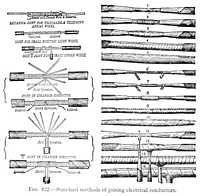
Fig. 422 - Standard methods of joining electrical conductors.
[...]
This information comes from
- Michael, Donald T (Working Group Chairman). IEEE Recommended Practice
for Electric Power Distribution for Industrial Plants, 5th Edition. New
York, NY: Institute of Electrical and Electronics Engineers, Inc - Standards
Board. Copyright 1976. ISBN 0471026867, LOC TK3141.I18.
(Additional information from this book is located on the Power
Systems page.)
The following information is excerpted from this book.
Cable Systems
[...]
Open Wire
This mode was used extensively in the past. Although it has now been replaced
in most applications, it is still quite often used for primary power distribution
over large areas where conditions are suitable.
Open-wire construction consists of uninsulated conductors on insulators
which are mounted on poles or structures. The conductor may be bare, or
it may have a covering for protection from corrosion or abrasion.
The attractive features of this method are its low initial cost and the
fact that damage can be detected and repaired quickly. On the other hand,
the uninsulated conductors are a safety hazard and are also highly susceptible
to mechanical damage and electrical outage from birds, animals, lightning,
etc. There is increased hazard where crane or boom truck use may be involved.
In some areas, contamination on insulators and conductor corrosion can result
in high maintenance costs.
Due to the large conductor spacing, open-wire circuits have a higher reactance
which results in a higher voltage drop. This problem is reduced with high
voltage and higher power-factor circuits.
Exposed open-wire circuits are more susceptible to outages from lightning
than other modes. The effects may be minimized though, by the use of overhead
ground wires and lightning arresters.
Aerial Cable
[...] Aerial cables may be either self-supporting or messenger-supported.
They may be attached to pole lines or structures. Self-supporting aerial
cables have high tensile strength for this application. Cables may be messenger-supported
either by spirally wrapping a steel band around the cables and the messenger,
or by pulling the cable into rings suspended from the messenger. The spiral
wrap method is used for factory-assembled cable, while both methods are
used for field assembly. A variety of spinning heads is [are] available
for application of the spiral wire banding in the field.
Self-supporting cable is suitable for only relatively short spans. Messenger-supported
cable can span large distances, dependent on the weight of the cable and
the tensile strength of the messenger. [...]
Spacer cable is a type of electric supply-line construction that consists
of an assembly of one or more covered conductors separated from each other
and supported from a messenger, by insulating spacers. [...] Uniform line
electrical characteristics are obtained through the balanced geometric positioning
of the conductors with respect to each other, by the use of plastic or ceramic
spacers located at regular intervals along the line. Low terminating costs
are obtained because the conductors are unshielded.
[...]
Insulators Home > Book
Reference Info > History of Electrical Systems and Cables
Contact: A.C. Walker