Materials and Types
The insulators used in connection with overhead systems employing bare conductors are composed almost invariably of glazed porcelain, although some moulded materials are used for low voltages, and glass has been used on the European Continent and in America for medium voltages. The British Standard Specification gives particulars of porcelain only, and requires that "the porcelain shall be ivory white, sound, free from defects, and thoroughly vitrified so that the glaze is not depended upon for insulation". This thorough vitrification of the porcelain is of paramoutn importance, since the presence of pores or other air-spaces will lower the dielectric strength. Any sealed-in impurities will also decrease the dielectric strength, and it therefore follows that porcelain for electrical purposes must be both thoroughly air-free and impervious to the entrance of gases and liquids. Apart from the above requirement, electrical porcelain is practically identical with the pottery which has come down to us through the ages, since the obvious requirement of high dielectric strength is inherent in all porcelain which is homogenous and free from impurities. The dielectric strength of mechanically sound porcelain is on the order of 15,000 to 17,000 volts for every one-tenth inch thickness. Actually, it is very difficult to manufacture perfectly homogenous porcelain of a thickness requires for certain types of insulator, and it is then necessary to adopt a two- or three-piece construction, the various pieces being fixed and glazed separately and then cemented together.
The ultimate strength of electrical porcelain, as measured on the standard ceramic test piece, is 100,000 lbs./sq.in. in compression and 7,000 lbs./sq.in. in tension. The figures realised on the larger sections used in insulators are lower than these, and may be taken as 40,000, and 2,000 to 3,000, for compression and tension respectively.
Very sound insulators are made from glass, its advantages being the very high dielectric strength of 35,000 volts per one-tenth inch thickness, and the possibility of adopting a one-piece design, no matter how large the insulator may be. It has also a lower coefficient of thermal expansion, which minimises the strains due to temperature changes; is transparent to heat rays, thereby heating up but slightly when exposed to sunlight; and is mechanically stronger than porcelain when under compression. In tension, it has about the same strength as porcelain. The disadvantages of glass are that moisture more readily condenses on the surface; and that in large sizes the great mass of material, combined with the irregular shape, may result in internal strains after cooling. Under ordinary atmospheric conditions, toughened glass is therefore limited to about 30,000 volts, while in dry climates it can be used up to 50,000 volts.
Although B.S. 137 does not include glass other than toughened, forms of untoughened glass are in current use. These are the ordinary lime-soda glass, and the boro-silicate glasses. Untoughened glass is used on the Continent and in America, for low and medium voltages, say up to 20 kV. Its resistance to continuous mechanical loads and temperature changes is poor compared with porcelain and toughened glass.
There are three types used in connection with overhead lines, viz. :
- Pin-type.
- Suspension-type.
- Strain-type.
Pin-Type Insulators
As the name suggests, the pin-type insulator is attached to a steel bolt or pin, which is secured to a cross-arm on the transmission pole. The above-mentioned British Standards Specification requires that the porcelain shall not engage directly with a hard metal screw. B.S. 137 recognises two methods:
- The provision of a taper thread cut on the head of the pin, which screws into a threaded soft metal thimble cemented into the insulator.
- The provisions of a cast lead thread on the steel spindle, which screws directly into a thread formed in the porcelain; on the continent the pin, which has a plain top, is still sometimes wrapped in hemp and the threaded porcelain screwed on.
For operating voltages up to about 25,000 with ordinary designs of insulator a one-piece construction can be adopted, up to about 45,000 volts a two-piece, up to 66,000 volts a three-piece, and beyond this a four-piece insulator. Recent progress in design and manufacture has enabled much thicker sections to be adopted, with the result that for working voltages up to 33,000 a single-piece construction is possible, and not more than two parts even in the largest sizes. Actually, the tendency is to use pin-type insulators for voltages up to 50,000 only, since they become uneconomical for higher voltages. This is because their cost increases much more rapidly than the voltage. [...]
According to Taylor, the ratio of average initial cost per mile of pin-type to suspension-type is about three to four or five, but the cost of replacement for suspension insulators is usually much lower than for pin-type.
Two typical porcelain pin-type insulators are illustrated in Fig. 10.1.
The characteristics of this type are as follows:
Type
Usual
Working
Voltage (kV.)Average
Puncture
Voltage (kV.)Height
(in.)Max.
Diameter
(in.)Seepage
Distance
(in.)Net Weight
of Porcelain
(lb.)11004
3.3
85
3 5/8
3 5/8
5 1/4
1 3/16
5063
6.6
120
4 1/4
4 1/16
6 3/4
1 3/4
5065
11.0
140
6 5/8
5 3/4
11 3/4
3 15/16
11253
33.0
250
9
10 3/4
29
23 5/8
The usual working voltage refers to insulators for use in an industrial atmosphere in this country. Smaller insulators are used in clean conditions.
The significance of these figures will be appreciated from the following notes. There should be sufficient thickness of porcelain between the line conductor and the insulator pin (or other metal work) to give a factor of safety of up to 10 against puncture, but the insulator should be designed so that it will spark-over before it will puncture. The ratio of the spark-over voltage to the working voltage is called the safety factor, and for pin-type insulators this factor is much higher for low voltages than it is for high. The present tendency is to use pin-type insulators for low voltages only, say up to 11 kV., for which the factors of safety are 8.3 dry and 5 wet.
With a wet insulator, the surfaces of the various pieces, or 'sheds' as they are sometimes called, have no insulating value, so that the total arcing distance is the sum of the shortest distances from the edge of one shed to the nearest point on the next lower shed, plus the distance from the edge of the next lowest shed to the pin. With a wet insulator, the arcing distance is thus a+b+c in Fig. 10.2(A). With a clean, dry insulator, the surfaces of the sheds have their proper insulating value, and the sparking distance is, therefore, the shortest distance from conductor to pin which avoids the insulator, e.g. a+b+c in Fig. 10.2(B). The pin must be long enough to make the vertical distance d in Fig. 10.2(A) greater than c; otherwise, in the case of an arc-over, the discharge will take place to the cross-arm instead of to the pin, thereby necessitating the renewal of the cross-arm. It should also be noticed that in the case of a steel cross-arm on a wooden pole, this should be connected to the earth wire of the pole; and in the case of a wooden cross-arm, the earthing wire should be brought to a metal strip laid along the top of the arm so that the pins of the insulators pass through it.
Porcelain insulators of ordinary design arc over at somewhere about 10,000 volts per inch, so that if the sum of the distances a+b+c [when] dry were 10 in., the insulator would arc over at about 100,000 volts. [...]
The insulator and its pin, or other support, should be sufficiently strong mechanically to withstand the resultant force due to the combined effects of wind pressure and weight of span (and ice load, if any). At terminal poles there is, in addition, the almost horizontal pull due to the tension of the conductor. This, in particular, causes such a great bending moment at the bottom of the pin, with pin-type insulators, this being transmitted to the cross-arm, that for a line insulated with pin-type insulators, it is desirable to use some type of strain insulator at all terminal or dead-ending poles. In connection with the mechanical strength, it is to be noted that the insulator is stronger than the pin. In fact, the pin should be designed as a cantilever, and the elastic limit of the steel should be just reached at the load for which the pin is designed. [...]


Suspension Insulators
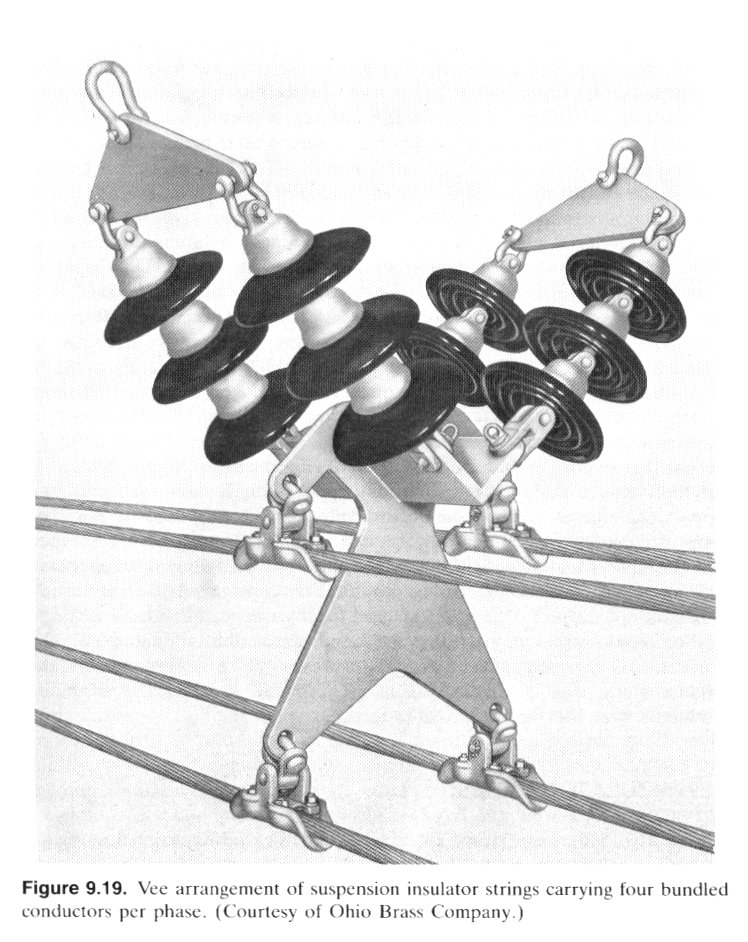
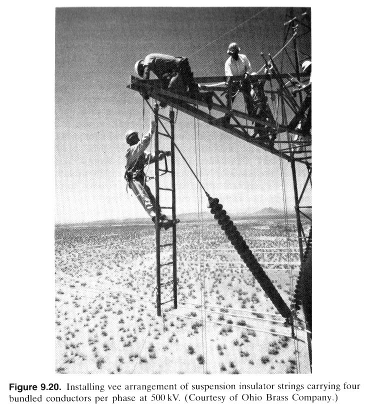
We have seen that the cost of a pin-type insulator increases very rapidly as the working voltage is increased. For high voltages this type is therefore uneconomical, and there is the further disadvantage that replacements are expensive. For these reasons, high-voltage lines are insulated by means of suspension insulators in which, as their name indicates, the line conductor is suspended below the point of support by means of the insulator or insulators. Several important advantages follow from this system.
- Each insulator is designed for a comparatively low working voltage, usually about 11,000 volts, and the insulation for any required line voltage can be obtained by using a 'string' of a suitable number of such insulators.
- In the event of a failure of an insulator, one unit - instead of the whole string - has to be replaced.
- The mechanical stresses are reduced, since the line is suspended flexibly; with pin-type insulators, the rigid nature of the attachment results in fatigue and ultimate brittleness of the wire, due to the alternating nature of the stress. Also, since the string is free to swing, there is an equalisation of the tensions in the conductors of successive spans.
- In the event of an increase in the operating voltage of the line, this can be met by adding the requisite number of units to each string, instead of replacing all insulators, as would be necessary with pin-type.
Owing to the free suspension, the amplitude of swing of the conductors may be large compared with that on a pin-type insulated line, and the spacings should therefore be increased.
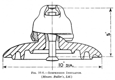
There are several types of suspension insulator, that illustrated in Fig. 10.4 being most frequently used in this country, having been adopted for the insulation of the Grid lines. It will be seen that it consists of a single disc-shaped piece of porcelain, grooved on the under-surface to increase the surface leakage path, and to a metal cap at the top, and to a metal pin underneath. The cap is recessed so as to take the pin of another unit, and in this way a string of any required number of units can be built up. The cap is secured to the insulator by means of cement. Various means of securing the pin have been tried, but all have been abandoned in favour of cementing. Mechanical methods of fixing have proved unsatisfactory since they caused concentrations of mechanical stress, which led to failure in service. On the other hand, cement acts as a good distributor of mechanical stress, and cemented insulators of good mechanical design have an excellent service record.
The usual diameter of this type of insulator is ten inches, since it has been found that this size gives a suitable ratio of spark-over to puncture voltage. Increasing the diameter raises the spark-over voltage, of course, but it also lowers the above ratio, and this is undesirable.
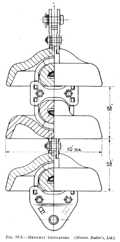
Another type of suspension insulator, the "Hewlett" insulator, is shown in Fig. 10.5. This has ten-inch discs, each disc having two curved tunnels which lie in planes at right angles to one another. Lead-covered steel U links are threaded through these tunnels, and are fastened to similar links on adjacent upper and lower units. Thus no cementing or special fastening is required, and the design is very simple. This ten-inch pattern has been found very suitable for lines up to and including 33,000 volts, where the conditions of mechanical loading allow of its use. Since the ultimate mechanical strength is decided by the steel links, and not by the porcelain, this pattern is very strong and has the peculiar advantage that the breaking of a porcelain disc will not allow the line to fall, or, in fact, interrupt the service, if a string of several units is used. Its disadvantage is that this construction is, of necessity, associated with high electrostatic stresses in the porcelain immediately between the links, so that the liability to puncture is greater than with other types.
The Hewlett insulator is also used as a strain insulator (see below), particularly on pin-type insulator lines up to 33 kV. It is supplied in various disc diameters from 6 in. to 10 in., and for mechanical working loads from 2,000 to 8,000 lbs.
The performance characteristics for single units of the ten-inch and six-inch discs are as follows:
Type
Spark-over
Voltage, Dry (kV.).Spark-over
Voltage, Wet (kV.).10-in. disc
75
48
6-in. disc
55
27
Strain Insulators
These insulators are used to take the tension of the conductors at line terminals and at points where the line is dead-ended, as for example some road-crossings, junctions of overhead lines with cables, river crossings, at angle towers where there is a change in direction of the line, and so on. For light low-voltage lines, say up to 11,000 volts, the shackle insulator is suitable, but for higher voltages a string of suspension-type insulators is necessary. Where the tension is exceedingly high, as at long river spans, two, three, or even four strings of insulators in parallel have been used. However, the present practice in this country is to avoid the use of multiple strings where heavy mechanical loads are required, and to use units of higher mechanical rating. Standard units are made for 4,000, 8,000, and 12,000 lbs. maximum working load, which suffice for all normal construction on lines up to 275 kV. For river crossings, it is necessary to use multiple strings.
It will be realised that when used as strain insulators, the discs are in a vertical instead of a horizontal plane. This may make some difference to the spark-over voltage [when] wet, the value for the standard ten-inch insulator being 55,000, and for the standard six-inch Hewlett insulator 33,000 volts.
Potential Distribution Over a String of Suspension Insulators
[...] The following results of an actual test on ten-inch suspension insulators show how the string efficiency depends upon the number of units in the string, and also on the condition (whether dry or wet). [S.O.V. = Spark-over Voltage]
No. in
series.S.O.V.,
Dry (kV.).String Effic.,
Dry. (Per cent.)S.O.V.,
Wet (kV.).String Effic.,
Wet. (Per cent.)1
75
100
48
100
2
140
93.4
90
92
3
195
86.7
128
89
4
245
81.8
166
86.5
5
295
78.8
205
85.5
6
345
76.7
245
85.1
7
395
75.4
280
83.4
8
445
74.2
320
83.4
9
490
72.8
355
82.2
10
535
71.4
385
80.3
[...] When [the string efficiency] is small, the top units are performing very little work, and adding further units has very little effect on the voltage across the unit adjacent to the line conductor. For high voltages, say over 100,000 volts, it is thus imperative that [the string efficiency] shall be large; otherwise, an impossibly large number of units per string will be required. [...]
In every case, the maximum voltage is on the bottom unit. [...]
Good results have been obtained by using standard insulators for most of the string, and larger units for that adjacent to the line, and possibly the next insulator above. Also, with comparatively light lines, it is possible to use the smaller Hewlett units for most of the string, and two or three standard 10-in. units at the bottom. In this way, the total number of units required, and therefore the cost of the string, can be reduced, but there is still the operating disadvantage that stocks of different-sized insualtors must be carried. Alternatively, the capacitances of the bottom units can be increased by fitting metal caps, or even by painting a portion of the top surface with a conducting paint. In practice, the method of capacitance grading is only suitable for very high-voltage lines, say 200,000 volts or over.
The voltage distribution is controlled in this [static shielding] method by the employment of a grading or guard ring, which usually takes the form of a large metal ring surrounding the bottom unit and connected to the metalwork at the bottom of this unit, and therefore to the line. This ring, or shield, has the effect of increasing the capacitances between metal work and line. [...]
With this method, it is impossible to obtain in practice an equal distribution of voltage, but considerable improvements are possible nevertheless. For example, tests on a certain 14-unit string gave 18.3 per cent. of the total voltage on the bottom unit unshielded, and 11.8 per cent. when shielded.
Incidentally, the grading shield serves the purpose of an arcing shield when used in conjunction with an arcing horn fixed at the top end of the string. In the event of a power arc following a flash-over due to some type of over-voltage, the arc will usually take the path between horn and shield, and stay clear of the insulator string.
Special Types of Insulator
Where the conditions of service depart from normal, for example, where there are smoke, chemical, or salt deposits, it may be necessary to use special designs of insulator, since insulators of normal shape will not operate satisfactorily. Also, in districts where lightning storms are frequent, or where there may be over-voltages which result in steep-fronted travelling waves, the electrical stresses set up are in the nature of an impact, and it may be found that insulators which operate with perfect satisfaction to over-voltages of line frequency may puncture readily to such steep-fronted waves. Hence, in such situations also, special designs are required.
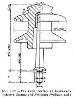
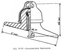
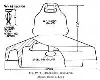
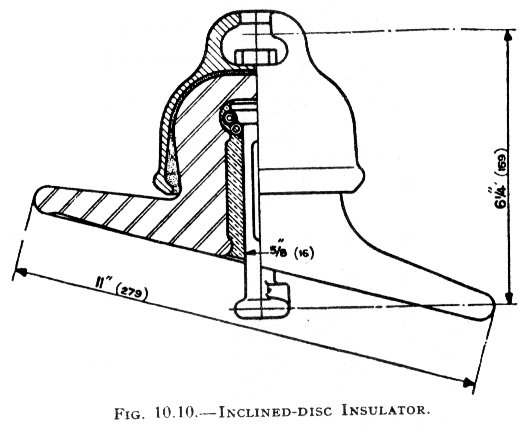
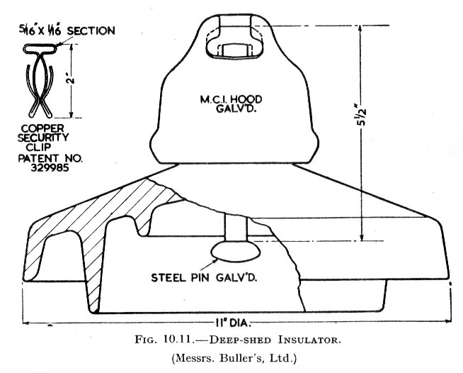
The requirements of anti-dirt insulators are: firstly, a long creepage distance; and secondly, a profile which derives the maximum benefit from the cleaning action of the rain. Fig. 10.9 shows a pin-type insulator designed with these ends in view: its working voltage is 11 kV., and its total creepage distance is 19 1/4 in. as against 12 3/4 in. in the normal design. (It has been found that in this country [Britain] it is necessary to use anti-dirt or anti-fog insulators in most areas. It is usual to specify a creepage distance of 1 in. per kV. of the phase-to-phase voltage.) The cleaning action of the rain is facilitated by the provision of a long waist which ensures a wide separation of the two sheds. Special anti-dirt suspension insulators have also been tried, one type having the discs arranged at a small angle instead of in the horizontal plane, as illustrated in Fig. 10.10. The various units were assembled so that the discs were inclined alternately to the right and left. Although this type gave good service in some localities, it was unsatisfactory for the following reason: Imagine the insulator clean, its leakage resistance thus being a maximum; during a fine spell there will be a gradual accumulation of deposit, which will have little effect so long as the atmosphere is dry. Prior to a spell of wet weather, there is usually a considerable increase in atmospheric humidity before the fall of any rain, and consequently the surface insulating property will break down, with possible spill-over of the insulator beforethe rain can wash the deposit away. This has been overcome by the provision of a long leakage path, one method being to design the insulator with a deeper shed than usual. An insulator of this type is illustrated in Fig. 10.11.
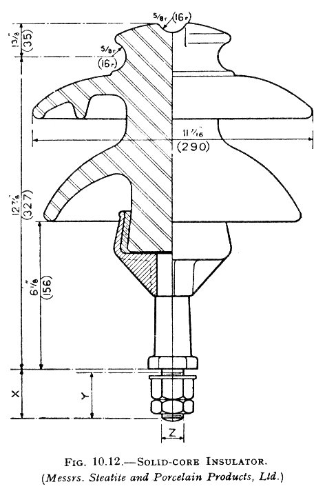
In order to avoid puncture under the action of steep-fronted voltage waves, it is essential that the intense electrostatic stresses in the neighbourhood of the pin shall be avoided. This is accomplished by doing away with the pin altogether and using a solid-core insulator whose base is secured to a shank of suitable shape. A pin-type insulator of this type, for a working voltage of 33 kV., is shown in Fig. 10.12.
It has been pointed out that the ideal design of insulator is one in which the surface coincides with an equipotential surface. With porcelain, this ideal can only be approximately attained, but Dr. H. B. Smith developed a suspension type in which the insulation was achieved by a wooden rod, and the shape of the electrostatic field controlled by means of an upper and lower metal shield. The design of a 110-kV. unit is shown in Fig. 10.13, from which it will be seen that the insulator proper is a wooden rod 2 in. in diameter. The upper metal shield is dished, and is 45 in. in diameter, while the lower metal shield is a spun copper ring formed by a 6-in. tube and having an outside diameter of 17 in. The overall length of the complete unit is 38 1/2 in. The tests results of this insulator are 280 kV. for dry and 200 kV. for wet flash-over. Corona formation is absent until the applied voltage reaches about 95 per cent. of the flash-over voltage. Owing to its central position, the insulating rod is situated in the region of minimum field strength, so that when electrical breakdown does occur, it is somewhere in the surrounding field and not along the rod. The mechanical strength is higher than that of a string of suspension units for the same voltage.
This insulator is described in order to show one of the ways in which the problem of the very high-voltage insulator has been tackled. It has not been adopted for two purely practical reasons.
- Neither wood nor any other organic material has been found suitable for out-door insulators;
- any design which depends on a uniform electric field is easily disturbed by dirt and moisture deposits.

Testing of Insulators
B.S. 137 groups the tests made on insulators into three categories: flash-over tests, sample tests, and routine tests. In each category, there is a group of individual tests. Flash-over tests are a design test taken to three insulators only to prove the correction of the design; sample tests are to prove the quality of manufacture, and are taken on 1/2 per cent. of the insulators supplied; routine tests are carried out on all insulators.
- Flashover Tests:
- 50 per cent. dry impulse flash-over test.
- Dry flash-over and dry one-minute test.
- Wet flash-over and one-minute rain test.
- Sample Tests:
- Temperature-cycle test.
- Mechanical test.
- Electro-mechanical test.
- Puncture test.
- Porosity test.
- Routine Tests:
- Electrical routine test.
- Mechanical routine test.
The following is a brief description of the above tests:
The test is made on a clean insulator mounted as far as possible in the normal manner. The impulse generator delivers a positive 1/50 microsecond impulse wave of amplitude such that about half of the impulses applied cause flash-over of the insulator. The polarity is then reversed, a negative 1/50 impulse being applied. There must be at least 20 applications of the impulse in each case, and the insulator must not be damaged.
A voltage of power frequency is applied to a clean insulator mounted as fas as possible in the normal manner, and the voltage gradually increased up to the specified value. This voltage is maintained for one minute. The voltage is then increased gradually until flash-over occurs. The insulator is then flashed-over at least four more times, the voltage being raised gradually to reach flash-over in about 10 seconds.
The insulator is sprayed with water of resistance 9,000 - 11,000 ohm-cm., drawn from a source of supply at a temperature within 10° C. of the ambient temperature in the neighbourhood of the insulator under test, and directed at an angle of 45 degrees, the volume of water being equivalent to a precipitation of 0.12 in. per minute. The insulator must withstand the test-voltage specified for one minute. The insulator with 50 per cent. of the one-minute rain test-voltage applied to it is then sprayed for two minutes, the voltage raised to the one-minute test-voltage in approximately 10 seconds and maintained there for one minute. The voltage is then gradually raised until flash-over occurs, and the insulator is then flashed at least four more times, the time taken to reach the voltage being in each case about 10 seconds.
In the temperature-cycle test, the insulator is subjected three times to the following temperature cycle: immersed for T minutes in a water-bath at not less than 70° C. higher than that of the main water, taken out, and immersed as quickly as possible in a main water bath and left in this bath for T minutes. T = (15 + W/3) where W = wt. of insulator in lbs. The insulator must withstand this series of tests without damage to the porcelain or glaze.
Applied to pin insulators and line post insulators. The test is a bending test, in which a load of three times the specified maximum working load (twice for a post insulator) is applied for one minute. There must be no damage to the insulator, and in the case of the post insulator the permanent set must be less than 1 per cent. In the case of the post insulator, the load is then raised to three times, and there must be no damage to the insulator or its pin (or pins). A permanent set-test is also made on the pin-type. A load of twice the maximum, applied for one minute, must not produce a permanent set of more than 1 per cent.
In this test, which is applied to suspension or tension units only, the insulator is mechanically stressed to a tension of 2 1/2 times the specified maximum working load, this being maintained for one minute. Simultaneously, 75 per cent. of the dry spark-over voltage is applied.
In the case of pin or post insulators, the voltage is applied between the pin and [the] lead foil bound over the top and side grooves. In the case of suspension units, between the metal fittings; the insulator is completely immersed in insulating oil at room temperature, and the voltage raised as rapidly as is consistent with correct measurement. The insulator must not be punctured. Alternatively, an impulse over-voltage test may be made in this case in air with the insulator arranged as for flash-over tests, a negative polarity 1/50 microsecond wave is applied of twice the amplitude of the negative 50 per cent. impulse flash-over voltage, as determined in test (a) above (i.e. a prospective voltage of twice the 50 per cent. flash-over voltage). Twenty such impulses shall then be applied. The procedure [is] to be repeated at prospective voltages of 2.5, 3, 3.5 ... [etc] times the 50 per cent. flash-over voltage, and continued until the insulator is punctured or the limit of the generator reached. The insulator, to pass the test, must not be punctured by prospective voltages of three times, or less, the flash-over voltage.
Pieces freshly broken from a complete finished insulator to show no signs of impregnation (when further broken) after being immersed for 24 hours in a 0.5 per cent. alcohol solution of fuchsin under a pressure of 2,000 lbs. per sq. in.
Pin insulators are inverted, and immersed in water sufficiently deep to cover the attachment to the neck groove; the spindle hole is also filled with water. The test is commenced at a low voltage, which is increased rapidly until a flash-over occurs every few seconds. The voltage is maintained at this value for at least five minutes, or if failures occur, for five minutes after the last punctured piece has been removed. At the conclusion, the voltage is reduced to about one-third of the test-voltage before switching off. With suspension units there is, of course, no necessity for water immersion.
After assembly, every string insulator unit is suspended in a horizontal or vertical position, and a tensile load 20 per cent. in excess of the maximum specified working load applied for one minute.
Impulse Ratio
[...] For insulators destined for service in districts where there is some form of atmospheric pollution, salt deposit, and so on, the special types designed for such districts are tested under conditions which approach, as far as possible, the actual working conditions. Thus, insulators can be tested in fog, with various kinds of deposit, or under salt spray.