Overvoltage and Flashovers
Insulators Home > Book
Reference Info > Overvoltage and Flashovers
Information from:
- Diesendorf, W. Insulation Co-ordination in High-voltage
Electric Power Systems. London, England (printed in Hungary): Butterworth
& Co (Publishers) Ltd. Copyright 1974. ISBN 0408704640, LOC TK1005.D53.
- Beck, Edward (Manager, Lightning Arrester Engineering Section, Westinghouse
Electric Corporation). Lightning Protection for Electric
Systems. New York, NY: McGraw-Hill Book Company, Inc. Copyright 1954.
LOC TK3248.B4.
- Lewis, Walter Wallace (Former Transmission Engineer for Central Station
Engineering Division, General Electric Company). The
Protection Of Transmission Systems Against Lightning. New York, NY:
John Wiley & Sons, Inc. Copyright 1950. LOC TK3248.L4.
- Rüdenberg, Reinhold. Transient Performance of
Electric Power Systems. Cambridge, Massachusetts: The M.I.T. Press
(originally McGraw-Hill). Copyright 1950. LOC TK3226.R8.
- Cotton, H. (Emeritus Professor of Electrical Engineering, University of
Nottingham). The Transmission and Distribution of Electrical
Energy. London, Great Britain: The English Universities Press, Ltd.
Copyright 1958. LOC TK3001.C65.
- Willheim, R.; Waters, M. Neutral Grounding in High-Voltage
Transmission. New York, NY: Elsevier Publishing Company. Copyright
1956. LOC TK3227.W5.
This information comes from
- Diesendorf, W. Insulation Co-ordination in High-voltage Electric Power
Systems. London, England (printed in Hungary): Butterworth & Co (Publishers)
Ltd. Copyright 1974. ISBN 0408704640, LOC TK1005.D53.
The 'Preface' states:
This book is concerned with one important area in the larger field of high-voltage
insulation: the insulation design and surge performance of high-voltage transmission
lines and stations, customarily referred to as 'insulation co-ordination'.
[...]
The 'Acknowledgements' states:
The seeds of this book were sown a number of years ago when the author lectured
on insulation co-ordination to a refresher school on Power System Engineering
initiated by Professor C. E. Moorhouse, Head of the Department of Electrical
Engineering at the University of Melbourne. In repeat schools held at various
Australian Universities, the section on insulation co-ordination was contributed
to by Drs. M. Darveniza and T. M. Parnell, both of the University of Queensland.
Building on the material so accumulated, the writer enlarged and consolidated
it on the occasion of a seminar he conducted at Rensselaer Polytechnic Institute,
encouraged by Dr. E. T. B. Gross, Chairman of Electric Power Engineering,
and aided by stimulating discussions with Drs. M. Harry Hesse and T. S. Lauber,
both professors of Electric Power Engineering at Rensselaer. These lectures
were published in 1971 by Rensselaer Bookstore, Troy, N.Y., under the title
'Overvoltages on High Voltage Systems (Insulation Design of Transmission Lines
and Substations)'. [...]
The following information is excerpted from this book.
Introduction
The reliability of supply provided by an electric power system, as judged
by the frequency and duration of supply interruptions to customers, depends
to a great extent on the surge performance of the system. Although there are
many other causes of interruptions, breakdown of insulation is one of the
most frequent. If the insulation were subjected only to the normal operating
voltage which varies within quite narrow limits, there would be no problem.
In reality, the insulation has to withstand a variety of overvoltages with
a large range of shapes, magnitudes, and durations. [...]
It is soon found that it is not always possible to provide insulation which
will withstand the highest stresses that may occur. An economic limit intervenes
well before the technical limit. The engineer places this limit at the point
at which the cost of achieving a further improvement in reliability cannot
be justified by the savings the reduced number of breakdowns may bring, which
are at any rate difficult to assess in money terms. He deliberately accepts
a certain probability of breakdown in the design of power systems. In this
respect his design philosophy differs from that of a civil engineer who designs
those structures whose failures could have catastrophic consequences to withstand
all forseeable stresses. [...]
Overvoltages
Overvoltages can be impressed upon a power system by atmospheric discharges,
in which case they are called 'lightning overvoltages', or they can be generated
within the system by the connection or disconnection of circuit elements or
the initiation or interruption of faults. The latter type are classified as
'temporary overvoltages' if they are of power or harmonic frequency and sustained
or weakly damped, or as 'switching overvoltages' if they are highly damped
and of short duration. Because of their common origin, temporary overvoltages
and switching surges occur together, and their combined effect is relevant
to insulation design. The probability of coincidence of lightning and switching
surges, on the other hand, is small, and can be neglected.
The prospective magnitudes of lightning surges appearing on transmission
lines are not much affected by line design; hence lightning performance tends
to improve with increasing insulation level, i.e. system voltage. The magnitudes
of switching surges, on the other hand, are substantially proportional to
operating voltage. As a consequence, here is a system voltage at which the
emphasis changes from lightning to switching surge design; this point is reached
at approximately 300 kV. In the 'extra-high voltage' range, up to the highest
existing system voltage of 765 kV, both lightning and switching overvoltages
have to be considered. For the 'ultra-high voltages' at present being investigated,
switching surges will be the main, though not the sole, criterion; insulator
pollution, in particular, will remain an essential design factor. [...]
Lightning Surges
[...] The potential of thunderclouds has been estimated to be at least
100 million volts.
A lightning stroke to earth usually appears to the eye as a single luminous
discharge, although sometimes rapid fluctuations of light intensity can
be seen. Photographs with rotating-lens cameras reveal that most strokes
are followed by repeat strokes which travel along the path established by
the first discharge, at intervals of 0.5 - 500 ms. [...]
The current at the point of impact can be considered either as a negative
current flowing into the ground, or a positive current flowing out of it.
For a small proportion of lightning flashes, the downward current is positive.
The current in the return stroke is in the range from a few kiloamperes
to about 260 kA. [...]
It has been established that many more discharges take place intra-cloud
and from cloud to cloud than between cloud and ground. The ratio of cloud
flashes to groundflashes varies between 1.5 - 3 in temperate zones, and
3 - 6 in tropical climates.
Starting in the late 1920s, a great number of field investigations were
conducted to ascertain the characteristics of lightning which affect overhead
transmission line performance. Unfortunately, even today the available information
is neither definite nor complete. [...]
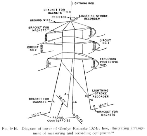
Lightning currents are measured either directly on high towers or buildings,
which are not really typical of transmission lines, or on the four corner
legs of transmission towers, which is inaccurate because of the unequal
division of leg currents and the presence of ground wires and adjacent towers.
[...]
The risk of lightning strikes to electrical installations is necessarily
related to the degree of thunderstorm activity. The only indicator readily
available from national meteorological services throughout the world and
the World Meteorological Organization in Geneva is isokeraunic level, or
thunderdays, defined as the number of days in a year or month when thunder
is heard at any particular location. Weaknesses of this measure, from the
transmission engineer's point of view, are that it does not distinguish
between ground strokes and cloud strokes, and does not recognize the varying
intensities and durations of thunderstorms. A somewhat better measure is
thunderhours, but the most appropriate measure is groundflash density. Attempts
are being made to obtain sufficient statistical data, and for this purpose
lightning flash counters have been developed. [...] Until more data from
this or similar devices becomes available, estimates of lightning intensity
will continue to be based on thunderday level.
Temporary Overvoltages
The significance of temporary overvoltages in respect to insulation co-ordination
lies in the requirement that surge diverters (lightning arresters) must
be able to reseal against sustained voltages, or risk destruction. Since
the protective level of any kind of surge diverter is proportional to the
reseal voltage, the insulation level and cost of equipment depends indirectly
on the magnitudes of temporary overvoltages. In the extra high voltage range,
temporary overvoltages cum switching surges determine the insulation of
transmission lines and consequently their dimensions and cost.
The main causes of power frequency overvoltages are: sudden loss of load;
disconnection of inductive loads or connection of capacitive loads; Ferranti
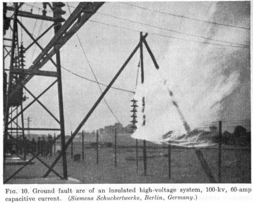
effect; and unbalanced ground faults. [...]
The duration of temporary overvoltages may vary from a few cycles, if intertripping
or voltage-dependent relay protection is provided, or a few seconds, if
reduction depends on automatic voltage regulators, to much longer periods
if human intervention is relied upon. [...]
A single line-to-ground fault causes a rise in the voltages to ground of
the healthy phases, which depends mainly on the effectiveness of neutral
earthing. For isolated neutral or suppressed coil systems, the potentials
of the healthy phases can exceed the line-to-line voltage; for solidly grounded
systems they will increase above their normal values but remain below line-to-line
voltage. Double line-to-ground faults may also produce increases in line-to-ground
voltages.
A measure of the voltage rise caused by single line-to-ground faults is
the 'earth fault factor', defined as the ratio of the higher of the two
sound-phase volrages to the line-to-neutral voltage at the same point of
the system, with the fault removed. [...]
Switching Overvoltages
It has already been pointed out that switching overvoltages are the criterion
by which the insulation of extra high voltage (e.h.v.) systems has to be
designed. The reduction of switching surges is therefore an economic necessity.
In the past, circuit-breaker design was directed towards reducing the overvoltages
caused by the interruption process. As these efforts were successful, it
was found that surges arising on energizing e.h.v. transmission lines became
more critical, and circuit-breakers were developed to control these closing
surges. Indications are that in the future, overvoltages accompanying the
initiation of short-circuits, which are uncontrollable, may establish the
next lower limit. The continuing reduction in switching surge magnitudes
may result in lightning performance again increasing in relative importance.
The absolute lower limit, as far as insulation exposed to the atmosphere
is concerned, will probably be set by insulator pollution.
The peak magnitude of a phase-to-ground switching overvoltage can be expressed
in 'per unit', relating it to the peak voltage to ground. A phase-to-phase
overvoltage is also expressed in terms of the highest voltage peak to ground.
Quite often the term 'overvoltage factor' is used to indicate the ratio
of the overvoltage to the peak of the system voltage prior to or after the
transient. This voltage may of course differ considerably from the highest
voltage for equipment, and to avoid misunderstandings, the reference voltage
and the conditions of the case ought to be clearly stated.
Switching surges are of a great variety of shape, magnitude, and duration,
corresponding to the great variety of initiating events. [...]
Techniques are available to keep switching overvoltages to values of the
order of 2 p.u. which permit economical insulation design of systems up to
765 kV. Refinements are possible and are being developed for practical application,
which should lower surge levels still further, as demanded for future systems
of 1100 kV and higher.
Disruptive Discharge and Withstand Voltages
[...]
Environmental Effects
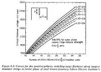
[...] Rain reduces the disruptive discharge voltage very considerably for
power frequency and switching impulses, but only little for lightning impulses.
The power frequency and switching impulse values for outdoor insulation
are accordingly measured in wet tests, while for lightning impulses only
dry tests are made. As an indication of the magnitude of the rain effect,
the power frequency CFO of a vertical insulator string in per unit of the
dry value is 0.8 at a precipitation rate of 1.5 mm/min, and 0.75 for a rate
of 3 mm/min.
Contamination is caused by a large variety of agents (coal and cement dust,
fly ash, salt spray, fertilizer, etc.) which, when moistened by fog or light
misty rain, can reduce the power frequency flashover voltage of porcelain
insulation to half or even to a quarter, depending on the type and deposition
density of the contaminant, and the frequency of washing rain. [...] An
approximate guide to insulation design for contaminated conditions is the
leakage distance per kV r.m.s. of the line-line operating voltage; it varies
from 15 to 30 mm for light and heavy pollution, respectively. For standard
cap and pin suspension insulators, the leakage distance is twice the spacing;
for fog-type, a factor of three is achieveable. [...]
Test Values
A large amount of test information has been accumulated over the years.
As operating voltages increase, experimental results are added for ever
longer gaps and insulator strings. Voltage limits imposed by the dimensions
of the laboratory or the capacity of the test equipment are removed by the
construction of new laboratories and by open-air testing. Wet tests suffer
from the difficulty that uniform artificial rain is hard to achieve, and
random errors are therefore large.
Different insulation arrangements have different characteristics; this
adds enormously to the test load. The most important arrangements required
in practice are: rod-rod gaps, used as protective gaps (also applicable
to phase-to-phase clearances; rod-plane gaps, representing a live conductor
above ground; parallel gaps, air clearance between phases or phase conductors
and ground wires; insulator strings for transmission lines, vertical, horizontal,
vee-strings, disc and long-rod, fog type, etc.; [and] support insulators
of various shapes. For e.h.v., the proximity of grounder tower metal affects
the flashover of insulator strings, and has been studied in tests of model
rigs with the objective of obtaining the optimum relationship of string
length and tower clearance. [...]
Lightning Impulse Test Characteristics

Lightning Overvoltages on Transmission Lines
Introduction
Lightning surges on transmission lines can arise by several mechanisms.
The least harmful are the voltages induced by strokes to ground in the vicinity
of the line. Lightning strokes to the phase conductors produce the highest
overvoltages for a given stroke current. [...]
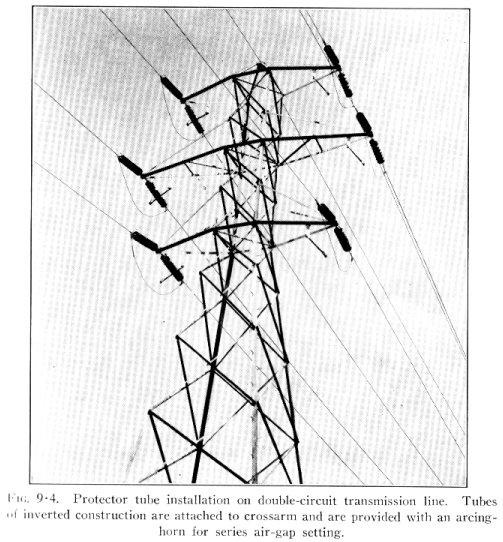
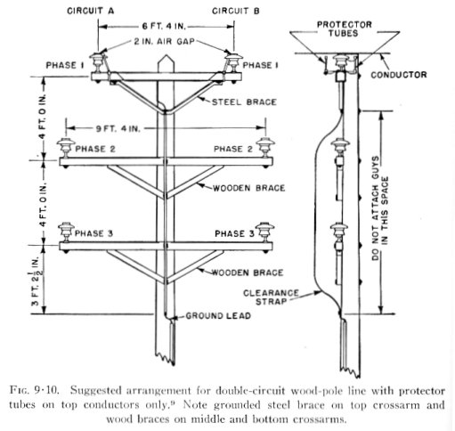
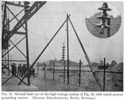
Circuit interruptions following flashovers can be avoided or at least mitigated
by arc suppression coils or 'protector tubes', devices which act in different
ways to achieve the same objective, extinction of power follow arcs. On
wood pole lines, a similar result can be achieved by designs which utilize
the arc quenching property of wood. [...]
Strokes to Nearby Ground
[...] A lightning discharge in the vicinity of the line will cause the
field to collapse and the charges on the conductors to be released. [...]
The induced surges are equal on all three phases, have usually positive
polarity, and their wave front is typically 10 microseconds. Crest values
depend on stroke current, distance from stroke, conductor height, and the
prescence or absence of shield wires. As these overvoltages rarely exceed
200 kV, flashovers due to electrostatic induction are unlikely on lines
of 33 kV or higher operating voltage. [...]
Strokes to Towers
The lightning currents in the stroke channel and towers flow at substantially
right angles to those in ground wires and phase conductors. [...]
It is clear that on towers of moderate height, a low tower footing resistance
will be very effective in reducing the tower top potential. [...]
On very tall towers, e. g. for river crossings, the potential may well
be determined by the terminating surge impedance, i.e. the combination of
tower and ground wire surge impedance, rather than by the footing resistance.
[...]
Strokes to Ground Wires
[...] As in the case of a stroke to the tower, this voltage is drastically
reduced by the arrival of a negative reflected wave from the tower base,
provided the tower footing resistance is low.
The maximum stress on tower insulation is of the same order of magnitude
as if the tower had been hit directly. This goes to show that strokes to
midspan can result in tower flashover though no midspan flashover has occurred.
[...]
The Lightning Performance of Transmission Lines
[...]
Wood Pole Lines
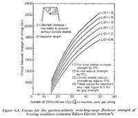
It is well known that wood can add considerably to the impulse insulation
strength of porcelain strings. Lusignan and Miller conducted a large number
of laboratory tests on the impulse strength of various wood/porcelain combinations.
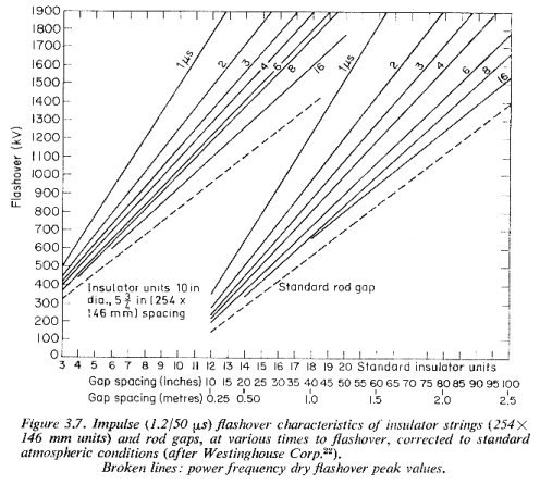
Their results are represented in a set of curves, Figure 5.4, which, in
conjunction with Figure 3.7, facilitate the determination of the strength
of the combination at various time lags, expressed as an equivalent number
of standard insulators. [...]
To extract the greatest benefit from the insulating properties of wood,
parallel air and wood/porcelain flashover paths on a pole top must be carefully
co-ordinated. This requires better accuracy which can only be obtained by
laboratory proving tests. [...]
Outage Rate and Sustained Outage Rate
[...] As a rough indication of the outage rates normally expected and considered
acceptable, the following figures are quoted:
- 11-66 kV rural lines : 0.7 - 3 outages / 100 km years
- 132 kV lines, in general : 0.6 outages / 100 km years
- Very important 132 kV and extra high voltage lines : 0 - 0.3 outages
/ 100 km years
Sustained outage rates are about one tenth of the above figures where automatic
reclosing is employed.
For steel tower lines with porcelain insulation only, the probability of
a flashover developing into an outage is approximately 0.85. [...]
Unshielded lines have a very high outage rate, but by taking advantage
of the arc quenching effect of wood, reinforced by automatic reclosing,
even cheaply constructed lines can achieve good reliability, comparable
with that of shielded lines. A reservation has to be made in respect to
lines which are so designed that they are likely to suffer interphase flashovers.
For these lines, a much less favourable performance must be expected.
If structures are designed to utilise the arc quenching property of wood,
they are in danger of the lightning current shattering the pole or crossarm.
The impulse arc penetrates into unseasoned wood, and laboratory tests show
that surge currents of less than 10 kA can shatter a crossarm or pole. In
well seasoned timber, on the other hand, service experience and laboratory
tests show that the arc hugs the surface and the only damage is usually
splinters of wood blown off. Pressure impregnated poles seem to retain moisture
for a longer time, and are therefore more susceptible to damage. Field data
indicate that, apart from newly constructed lines, the incidence of permanent
damage on wood pole lines is low. [...]
The Switching Surge Design of Transmission Lines
General
For system voltages below approximately 300 kV, switching overvoltages
are not critical. The exact voltage at which switching surges become the
more important criterion depends on many factors but mainly on the switching
surge level. For this reason it is desirable to reduce the per unit switching
surges for increasing system voltages. [...]
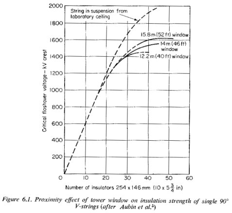
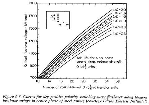
In the design of an economical tower, it is necessary to take account of
the proximity effect of grounded metal, which accentuates the already unfavourable
'saturation' characteristic of large air gaps. The effect is illustrated
in Figure 6.1 for the centre phase of a 735 kV tower; for outer phases it
is less severe. The main problem is the co-ordination of string length and
clearances to tower legs and truss. [...]
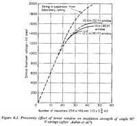
Tower Insulation Design
For many new and important e.h.v. projects, the tower dimensions and withstand
voltages were determined by special tests on tower mock-ups and full scale
towers, the tower window being the most critical. [...]
Application to Future Ultra-High Voltages
A great amount of laboratory and theoretical work is in progress for the
purpose of assessing the feasibility and economy of system voltages in the
range from 1000 to 2000 kV, and for acquiring the required design data.
[...]
At 765 kV, a switching surge level of 2 p.u. requires a conductor-to-tower
clearance of about 5.3 m; at 1500 kV the corresponding figure is 19 m. if,
however, the surge level is reduced to 1.5 p.u., [...] a clearance of 11
m would be sufficient. The clearance could be further reduced to 8 m at
1.35 p.u. maximum surge. This very low surge level could probably be achieved
for energising transients, but fault initiating overvoltages and containment
conditions may set the limit at about 1.5 p.u.
Ground clearance would be about 18.5 m. Allowing for vehicles and safety
margins, a crossarm height of about 48 m is required. With such huge tower
dimensions, every possible economy has to be explored. One way would be
to ascertain, by extended analysis, the exact shape of all likely switching
surges, and to design for actual waveshapes instead of the most onerous.
[...]
The Insulation Co-ordination of High-voltage Stations
Principles
The insulation design of high-voltage stations must be based on different
principles from those applying to transmission lines. Firstly, stations
generally contain transformers and other valuable equipment with non-self-restoring
insulation, which must be guarded most carefully against internal breakdowns.
Secondly, since they have vital functions to fulfill in the power system,
even the risk of flashover in air, with the accompanying disturbance to
normal operation, must be kept to a minimum.
In important stations, protection against lightning surges requires the
establishment of a protective voltage level by means of shunt-connected
protective devices. [...]
Below about 300 kV system voltage, switching surges are as little a critical
factor in stations as on transmission lines. If the BIL [lightning impulse
withstand level] is chosen correctly relative to the prevailing protective
level, the equipment will also have adequate switching surge strength. [...]
Overvoltage Protective Devices
Only rod gaps and surge diverters (lightning arresters) will be considered,
disregarding devices of more or less historical interest. [...]
The ideal requirements for shunt-connected protective devices can be summarised
as follows:
- They must not spark over under temporary voltages under any but the
most exceptional circumstances.
- Their volt/time curve must lie below the withstand level of the protected
insulation in any time region in which protection is needed. The margin
between two curves must be adequate to allow for the effects of distance,
polarity, variations in relative air density, humidity, ageing of the
insulation, and likely changes in the characteristics of the protective
device.
- They must be able to discharge high-energy surges without changes in
their protective level or damage to themselves or adjacent equipment.
- After discharging a surge, they should reseal (i.e. become non-conducting)
in the presence of temporary overvoltages. (Surge diverters can be destroyed
by power follow current.)
Rod gaps are simple and cheap, but do not meet all requirements, in particular
that of resealing. [...] Moreover, as no current-limiting resistor is used,
the impulse voltage collapses on sparkover to zero; if the gap is installed
near a transformer, the winding can be subjected to a very large step impulse
which places dangerous stresses on the turn insulation.
Nevertheless, rod gaps can provide reasonable protection where the isokeraunic
level is low and the front times of lightning surges are controlled by the
use of overhead ground wires and the prevention of backflashovers near the
station.
The basic elements of a surge diverter are the sparkgap, which acts as
a fast switch, and the non-linear resistor. [...] Pre-ionization of the
gap assists in ensuring quick and consistent sparkover. [...]
The lighter designs of surge diverter cannot cope with such long duration
currents [of 2000 microseconds], and they must not be allowed to operate
for line discharges. Heavy duty surge diverters with 'assisted' or 'active'
gaps are not so restricted.
A vital property of the gap is its ability to interrupt power follow current.
For any gap design, there is a maximum power follow current, of 100 - 300
A, which it can safely interrupt without special measures. [...] Fewer resistance
elements could be used it a higher current could be interrupted by the gap,
thus achieving a lower discharge voltage characteristic. This idea led to
the development of 'active' sparkgaps which use the magnetic blow-out effect
to increase the maximum gap interrupting current. [...]
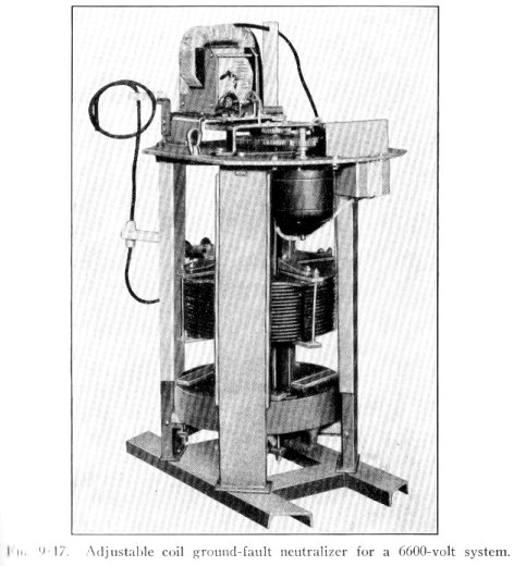
During lightning discharges, the high coil voltage induced by the steep
surge sparks auxiliary gaps, by-passing the coils. The auxiliary gaps extinguish
as soon as power follow current starts to flow. The magnetic field, aided
by the horn shape of the main gap electrodes, extends the length of the
arc and drives it into an arc cooling chamber of refractory material; the
increasing arc voltage rapidly forces the current to zero. [...]
Stations With Protected Zone
An open line breaker or disconnect switch presents the problem of guarding
against flashover of the open contacts. Preferential flashover to ground
on the line side is desirable, but to achieve it by differential insulation
is expensive. The provision of surge diverters on the line side, though
ideal, is too costly a solution for the relatively rare occasions when the
line is disconnected.
Rod gaps can be a satisfactory compromise if carefully adjusted so that
there is a small probability of sparkover. When the line is connected to
the station, they must not sparkover or they would vitiate surge diverter
operation. With the line disconnected, a line outage would not interrupt
power, but may be an operational inconvenience. If a line is out of service
for any length of time, the problem can be solved by grounding the line.
[...]
Stations Without Protected Zone
The absence of a shielded and well earthed protected zone, as one might
find in distribution systems, implies that for close-in strokes the current-limiting
effect of line surge impedance is missing, and the steepness of the incoming
voltage wave may be insufficiently attenuated. It is therefore essential
that a surge diverter should be located at the transformer terminals and
the lead length eliminated in order to suppress the distance effect. The
choice of BIL should be based on the higher discharge voltages expected
for the higher diverter current and front steepness. There is, however,
an economic limit to the expenditure on surge protection that can be justified.
An efficient transformer exchange and repair service may help to keep overall
costs down. [...]
This information comes from
- Beck, Edward (Manager, Lightning Arrester Engineering Section, Westinghouse
Electric Corporation). Lightning Protection for Electric Systems.
New York, NY: McGraw-Hill Book Company, Inc. Copyright 1954. LOC TK3248.B4.
The 'Preface' states:
Lightning, depending on the point of view, is awesome, terrifying, beautiful,
micheievous, destructive, and uncontrollable. The engineer has no objection
to some of these characteristics, but to protect his own handiwork he has
had to do something about the last two. He has not yet found ways of preventing
the formation of strokes, or of making definite areas stroke-free. However,
he has devised means of controlling the energy released in the struck object,
and thus is able to minimize its destructive effects by applying protective
measures. It is the purpose of this text to present the fundamental considerations
involved in lightning protection, particularly for alternating-current systems
and apparatus, and to describe the uses, functions, principles of operation,
performance, and typical construction of lightning arresters. [...]
The following information is excerpted from this book.
The Need for Lightning Protection
The objects of lightning protection are to allay fears and engender peace
of mind, to prevent annoying shutdowns of lights, radios, and movies during
thunderstorms, to avoid costly interruptions of manufacturing processes powered
by electricity and expensive outages and damage on electric systems, and to
save property and lives. It needs no further justification.
Throughout the world, there are on the average some 44,000 lightning storms
a day, and about 100 lightning strokes per second. To the land area of the
United States, it is estimated that there are 29.5 million strokes in a year.
If you are reading this chapter during July or August, about 910 strokes will
hit the United States while you are reading it. During the winter months,
the figure would be about 140. [...]
The people who practice lightning protection to the highest degree are the
operators of electric systems. Without lightning protection such as arresters
and shielding, systems would be subjected to frequent service outages and
damaged equipment. If there were no lightning arresters, they would have to
be invented quickly. In the early days of system operation, before adequate
lightning arresters had been developed, much trouble occurred. In some cases,
systems were shut down when a storm came up. This stimulated the development
of arresters to prevent interference with the service. The purpose of lightning
protection on electric systems is to ensure, as far as possible, the maintenance
of an uninterrupted supply of powers to users, regardless of the mischievous
attempts of lightning to disturb it. [...]
In exposed, unprotected systems, lightning is one of the principal causes
of outage. Outages cost the good will of utility customers; they result in
serious losses in time and money to power users and to utilities as well,
in restoring service and the replacing of damaged equipment. [...]
For many years, a gradual process of interconnecting utility systems has
gone on. The real purpose of this is to reduce the amount of generating capacity
that must be available for emergencies. Interconnection permits the exchange
of power during an emergency. During World War II, interconnection was stimulated
by the paramount need for reliable power and by the difficulty of obtaining
equipment for standby purposes. These interconnections, consisting generally
of transmission lines, transformers, and switchgear, would be unreliable themselves
and uneconomical without lightning protection to ensure that the means of
power transfer are dependable. Without interconnections, utilities would have
to install a great deal of spare, and normally idle, capacity to take care
of emergences and thus to provide the same reliability of power supply that
now exists.
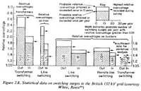
Statistical information on the relative performance of protected and unprotected
systems has been accumulated by experience and as the result of lightning
research in the field. One utility has reported the following data on distribution
transformers with and without lightning arrester protection.
|
Nature of trouble |
Troubles per year per
100 distribution transformers |
|
Without arrester |
With arrester |
|
Primary fuse blown only |
25.6 |
2.2 |
|
Transformers burned out |
2.4 |
0.3 |
|
Minor damage |
1.6 |
0.22 |
|
Total |
29.6 |
2.7 |
Typical costs of restoring service are: renewing blown fuse, $5 to $10; repairing
or replacing damaged distribution transformers, $75 to $90; minor damage,
$10 to $15.
These data indicate the benefits to be derived from adequate lightning protection.
They do not take into account the losses and inconvenience to the ultimate
consumer.
Concerning substation equipment, data are not available in the same form.
However, measurements of lightning currents discharged through arresters in
service in substations provide information on what would have happened had
lightning arresters been omitted. Research of this kind in the field has shown
that, in regions of average lightning-storm frequency and intensity, such
as in the general locality of Pittsburgh, lightning arresters in exposed substations
will discharge appreciable currents on the average of 1.5 times per year.
By calculation based on the magnitude of the currents measured, the magnitude
of surge voltage that would have appeared at the arrester location if no arrester
had been there can be determined. It has been found that 80 per cent of the
discharges mentioned above are the result of disturbances sufficiently severe
to have caused flashover or damage in the substation had no arrester been
provided. Thus the substation might suffer an outage or be damaged 1.2 times
per year, or six times in five years, if not protected.
Considering transmission lines, accumulated data indicate that in any one
year, the number of service interruptions or outages on unprotected lines
in lightning territory may vary from none to 2.3 per mile, with an average
of 0.4. On a transmission line 50 miles long, this would mean 20 outages in
a year, a serious interference with the transfer of power. Lines protected
by shield wires or expulsion arresters of the transmission-line type show
much better performance. Shield-wire-protected high-voltage lines are in operation
in severe lightning territory, with only zero to one lightning outage in several
years.
Lightning protection on electric systems prevents service outages and equipment
damage. Furthermore, the control of the lightning voltages that can appear
on systems and at apparatus makes possible economies in equipment insulation.
Protection makes the task of maintaining an electric system easier and less
expensive, because it decreases the need for line and apparatus repair and
replacement and reduces the necessity for service trips to restore power.
These factors save money and annoyance not only for the utilities but also
for the ultimate consumer. Lightning protection promotes his good will and
helps to kepe the rates for power low.
Lightning
[...] The greatest impetus to the study of lightning and its effects was
given by the beginning of electric transmission, commencing with Morse's telegraph
line. Lightning waxed in importance as the electrical industry grew. Intensive
study has continued to this day, and will go on far into the future. [...]
The only known way to cope with lightning is to humor it by giving it a good
path to ground, its ultimate goal. Strokes are too powerful to be resisted
by any device within man's present knowledge, and, as yet, no means are known
to prevent them.
Direct-Stroke Shielding
[...] If the wire has no direct metallic connection to ground, the flow of
lightning current into it will produce high voltages. Flashover to ground
will probably occur. If the wire is grounded frequently and well, it is feasible
to prevent high voltage. Such a wire also provides a protected are which is
then a tent-like zone parallel to the wire. Another wire within this shielded
zone is not likely to be struck directly. This is the principle of the shield
or overhead ground wire widely used on transmission systems. The shielding
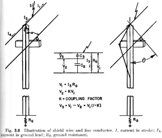
angle that provides 0.1 per cent exposure is, generally speaking, about 30
degrees, depending on the heights above ground. The shielding angle is the
angle between the vertical and a line drawn through the shielding and the
shielded conductors, the line lying in a plane perpendicular to the conductors.
It is shown in Fig. 3.8 as the angle.

A simple arrangement on wood poles of one line conductor with a single shield
wire is shown in Fig. 3.8. In the left-hand view, the grounding conductor
runs down the pole. When the shield wire is struck, currents flow as indicated
in the figure. The ground resistance of the connections to earth, and the
clearances between the line conductor and the down lead, are important. [...]
Figure 3.8 should be regarded as illustrative. It would apply only to single-phase
extensions of three-phase four-wire multigrounded neutral systems with the
neutral wire at the top of the pole. Such circuits are in operation. In the
higher-voltage transmission systems, where shield wires are most prevalent,
the circuits are three-phase, and there may be more than one circuit on the
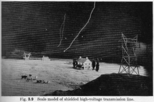
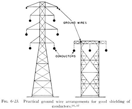
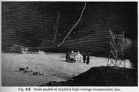
poles or towers. There may be two shield wires. Figure 3.9 is a picture of
a small-scale model of a high voltage line with two shield wires, such as
is common in high-voltage transmission. It is being struck by laboratory lightning
during an investigation of the factors that enter into proper shielding.
[...] The purpose of shield wires on transmission lines is to prevent flashovers
of the line insulation. The line conductors will still be subjected to transient
voltages which, although below the flashover value of the line insulation,
may be sufficiently high to endanger the insulation of connected apparatus.
This voltage may appear by coupling with the struck shield wire or from a
backflash. To safeguard the equipment tied to the system, some means of limiting
the voltages that can appear at the equipment must be provided. This is the
principal field of lightning arresters. Lightning arresters are used whether
the lines are shielded or not. However, in adequately shielded systems, the
duty on arresters is less.
Impulse Voltages and Insulation
The danger to electric systems and apparatus comes from the potentials that
lightning may produce across insulation. This may be, for example, the air
around an insulator supporting a conductor on a tower or pole, a transformer
or circuit-breaker bushing, or the liquid or the solid insulation in a transformer
or breaker or cable. If the potential caused by lightning exceeds the strength
of the insulation, a flashover or a puncture results, causing a short circuit
and a power outage. If a power arc follows, there may be disastrous results
in damage to equipment whose repair may cost considerable time and money.
The voltages ma be produced in either of two ways: by direct contact of the
stroke with a conductor, or by induction from a nearby stroke. Direct contact
injects the stroke current into the conductor, and it is obvious that high
voltage will appear in the system conductors since they are not grounded,
except possibly through high impedance. If a stroke hits near a line conductor
without actually making contact with it, it may, nevertheless, induce potentials
in the system. As the stroke leader approaches the earth, the elctrostatic
and electromagnetic fields associated with the main stroke discharge may also
induce potential in nearby wires. Although the induced voltages may, under
favorable conditions, reach magnitudes theoretically as high as 1 million
volts, they are generally lower. The potentials usually associated with direct-stroke
contact are higher. In high-voltage systems, such as 69-kv or higher, the
insulation is generally sufficient not to be endangered by induced voltages.
On low-voltage systems, induced voltages are a hazard. [...]
Five [suspension] insulators are used very generally on 69-kv transmission
lines, and the curves show that this line insulation can be protected reliably
against flashover by a 69-kv expulsion arrester. The sparkover of the 73-kv
valve arrester, a rating commonly used on 69-kv systems, is still lower and
also flatter. [...]
One of the most widely used and most important pieces of apparatus on a-c
systems is the transformer. The major proportion of lightning protection is
devoted to the transformers, in order that they may be kept intact and that
power may continue to flow throughout the system to the ultimate consumer.
A transformer is a more complicated arrangement of wires, iron, and insulation
that a bushing or an insulator. Not only do lightning voltages impressed on
transformers subject the bushings to impulse voltage, but surge voltage penetrates
into the winding-to-core insulation, and the insulation between windings.
The complete transformer should be able to withstand the voltages that may
occur at its terminals when protected by suitable lightning arresters. [...]
Lightning Arresters: General
Lightning protection by arresters involves taking care of the lightning currents
when they get into the system, without permitting voltages that endanger apparatus,
and without permitting a service outage. [...] If lightning strikes a circuit,
transient currents flow in the system. [...] If the flow of the current is
not obstructed by impedance or insulation, the voltages between points in
the path that are electrically adjacent are moderate. However, if the flow
is obstructed, very high voltages may appear because the lightning current
puts forth every effort to get to ground. If the obstruction consists of insulation,
the voltage developed across the insulation may be sufficient to puncture
it or flash around it, thus providing a means for the lightning to get on
its way, but also producing a short circuit and a power outage and, possibly,
costly damage to the insulation. A lightning arrester provides an easy path
for the lightning current to get around the insulation so that the high voltage
will not appear. The by-pass, however, must be such that it does not interfere
with the supply of power to the user. [...]
A lightning arrester may be looked upon as a very fast switch or circuit
breaker connected around the insulation to be protected. It is a breaker that
is normally open, but is able to close immediately when a transient voltage
of a predetermined magnitude appears, and then able to reopen speedily after
the transient has disappeared. The closing mechanism in a lightning arrester
is usually a spark gap of some form. This is normally insulating, but becomes
conducting by sparking when the transient voltage reaches the spark potential
of the gap. By this sparking, the circuit for the lightning current is made.
[...] The power or system current that flows in an arrester or gap, or around
an insulator, after it has sparked is called 'follow current'. It is a very
important quantity in the design and application of arresters. [...]
Simple spark gaps, such as rod, needle, horn, or sphere gaps, are not lightning
arresters. Although they can be made to provide a certain degree of protection
against overvoltages, they are unable to interrupt the follow current. It
is well known that, even though it may take a high voltage to break down an
insulating wall of air or any other gas, it takes very little voltage to keep
an arc going after it has once been started; as it may be by a spark, for
instance. Consequently, the operation of plain gaps produces a short circuit
that must be cleared by operation of a circuit breaker or fuse somewhere else
on the system. This means a service outage. Thus there is a sharp distinction
between plain gaps and arresters. The lightning arrester takes care of the
follow-current interruption within itself, without permitting an outage. [...]
Simple spark gaps are used sometimes instead of lightning arresters, because
they are less expensive. [...] The simple spark gap cannot stand on its own
feet, and is likely to promote outages rather than to prevent them. The attribute
that has from time to time attracted users is its relatively low cost.
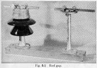
Spark gaps will limit surge voltages and, if the gap spacing is chosen judiciously,
will protect apparatus against damage by overvoltage, although at the cost
of system outages. In the practical use of gaps, rod gaps are most generally
used. A rod gap is simply an air gap between the ends of two square rods,
suitably supported on insulators. (Fig. 5.1). Variations of these are sometimes
used, such as rings supported on pillar insulators, or at the ends of strings
of suspension insulators, or short rods attached to bushings.
[...] Sphere gaps are not practical for this use because their spark potentials
are altered appreciably by rain. Therefore, they would have to be housed,
which increases the cost. Furthermore, the sphere gap very likely would be
severely burned by the power arc accompanying its first discharge, whereby
its sparkover characteristics would also be altered. Thus, protective gaps
are more or less restricted to rods or rings, which are not so susceptible
to weather conditions, and which can suffer a considerable amount of burning
by arcs without significant change in sparkover characteristics. [...]
The expulsion arrester is like an expulsion fuse with the fuse link omitted.
[...]
The valve arrester must perform the same functions as the expulsion arrester.
It carries them out in a similar fashion by a somewhat different process.
[...]
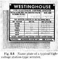
Basic information on a name plate for a high-voltage valve arrester would
be the manufacturer's name, the type, the voltage ratings, and catalogue number.
A typical name plate is shown in Fig. 5.6. The type indicates the surge-current
capacity; the type and voltage rating together indicate the performance characteristics,
usually published in the manufacturer's literature; the voltage rating gives
the operating limit from the standpoint of power-frequency voltage; and the
catalogue number is the final definite indentification.
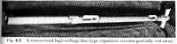
Expulsion Arresters for the Protection of Transmission-line Insulation
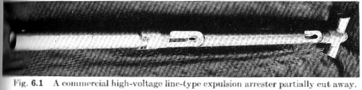
[...] The transmission-line type of expulsion arrester consists of the arcing
chamber and the external series gap. The arcing chamber is a tube of gas-evolving
material, usually horn fiber. The arc takes place in the bore of the tube,
between metal electrodes placed in each end of the tube. A sectional view
of a commercial arrester is shown in Fig. 6.1.
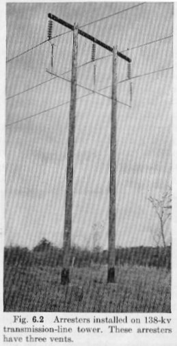
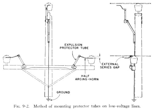
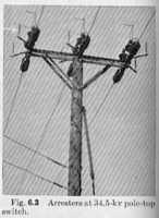
[...] The series gap is usually not physically an integral part of this type
of arrester. It is usually made at the time of installation, by spacing the
line end of the tube a proper distance from the live line conductor, as in
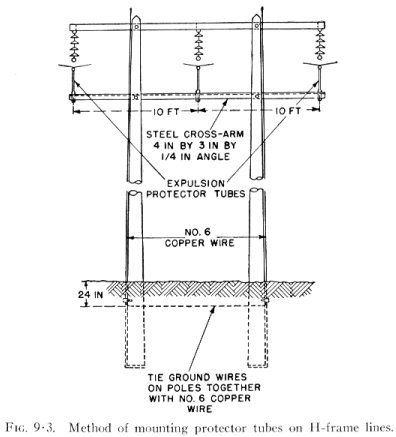
Fig. 6.2. The top of the tube may be provided with an arcing horn suitably
shaped to reach toward the line conductor, as in Fig. 6.3, or to maintain
a constant gap length in the case of conductor swing, as in Fig. 6.2. The
other end of the tube is connected to ground.

The simplicity of the device is apparent from the illustrations. This is
an important factor in its construction, because it is essential that an arrester
for transmission-line protection be inexpensive. Practically speaking, the
line-type expulsion arrester is the only one that is used for this purpose.
Other types of arresters could be used, but they are too expensive. Cost is
an important consideration, because any device to prevent lightning flashovers
on transmission lines must compete with the overhead shield wire. The choice
between shield wires and arresters is entirely one of economics. In general,
it may be said that, if a new transmission line is to be built from the ground
up, shield wires will be found to be the cheaper, or at least not more expensive
than expulsion arresters. In the case of an existing line that has no ground
wires, if it is desired to decrease the lightning outages, it is usually found
that expulsion arresters are less expensive than adding adequate overhead
shield wires to the already existing line. These general statements are subject
to qualifications, as is always the case in engineering problems. New high-voltage
transmission lines have been built with expulsion arrester protection in preference
to ground wires. In some special cases, arresters are more effective than
it is feasible to make shield wires, when it is not possible to secure low-resistance
grounds. In some cases, it may be desirable to equip certain poles or towers
on shield-wire-protected lines with arresters also. On certain medium- and
low-voltage lines, it may be possible to obtain good performance with arresters
at less cost than with shield wires. Where the cost and outage performance
of the line are comparable, the overhead shield wire is to be preferred.
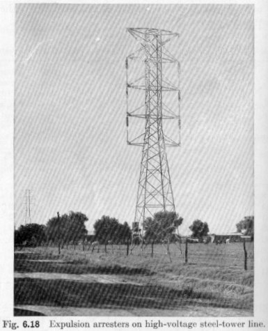
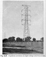
[...] If arresters are installed on the same pole or tower with the insulators,
as in Fig. 6.18, so that they are in parallel, the voltages across the insulators
are limited very closely to the voltages permitted by the arresters. [...]
The ground connection plays no part in this voltage. Even if the resistance
of the earth connection is high and the tower or pole is raised many kilovolts
above true earth potential, the potential around the insulators is still dependent
entirely on the arrester. In locations where it is difficult to obtain low-resistance
grounds, the transmission-line arrester has an advantage over the overhead
shield wire for this reason. The ground resistance obviously should not be
so high that it reduces the follow current to values below the minimum rated
current of the arrester. Overhead shield wires, as in Fig. 6.18, eliminate
that consideration.
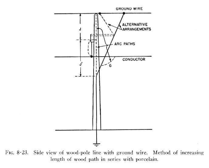
In some cases, the conventional line insulators may not have a sufficiently
high impulse flashover voltage to be protected by the applicable rating of
expulsion arrester. The addition of wood in series with the line insulation
will raise the impulse flashover voltage. This fact is frequently used to
advantage in the construction of transmission lines with or without arrester
protection.
Wood, although a good structural material, is not a reliable insulator for
continually applied voltage. When wet, its resistance decreases, and appreciable
leakage currents will flow, which eventually produce carbonized paths and
may cause fire and flashover. Therefore, porcelain insulators are used to
insulate the working or system voltage. However, for the short durations of
lightning surge voltage, wood even if wet possesses good insulating qualities.
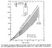
Considerable study has been devoted to this subject. [...] For a general rule
of thumb, a conservative value for the critical impulse flashover of wet wood
is 50 kv per foot. This may be added directly to the critical flashover of
the porcelain insulation in series with it. If, for example, the critical
flashover of a certain porcelain insulator is 200 kv, the addition of 2 feet
of wood in series with the insulator will give a conservative critical flashover
of 300 kv for the combination. The benefits to be gained by taking advantage
of impulse strength of wood are considerable. [...]
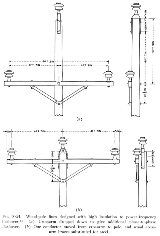
Steel-tower lines have been built with wood crossarms to raise the impulse
level of the line, and, in construction of modern wood-pole lines, the use
of metal crossarms and metal crossarm braces is generally avoided. By using
wood-pole construction, low-voltage lines can be given impulse strengths as
great as, or greater than, high-voltage lines on steel towers. [...]
Wood has one drawback from the standpoint of flashover. If it is stressed
by a severe lightning discharge, it may splinter or shatter and require replacement.
However, with the proper use of ground wires or expulsion arresters, this
can be avoided and the full benefits of wood utilized.
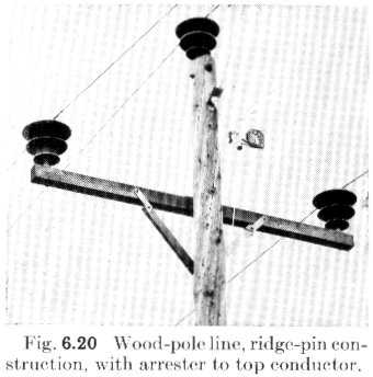
An economical use of line-type expulsion arresters can be made on wood-pole
lines of so-called ridge-pin construction, shown in Fig. 6.20. The ridge-pin
appelation derives from placing one conductor on a pin insulator fastened
to the ridge of the pole. The other two conductors are mounted at the ends
of a crossarm. This gives a triangular conductor configuration. If the shielding
angle of the top conductor is correct - for example, if the conductors were
spaced at the vertices of an equilateral triangle - the top conductor will
shield the other two from direct lightning strokes. Expulsion arresters applied
to the top conductor will discharge lightning current and will thus prevent
outages on it, while the shielding provided by the top conductor prevents
lightning flashover on the other two conductors.

[...] On transmission lines, all flashovers do not cause short circuits and
consequent system outages. Some flashovers are not followed by sustained system
faults. [...]
In the case of high-voltage steel-tower lines less than 100 miles long, about
85 per cent of the lightning flashovers result in power follow and circuit
outage. On such lines more than 200 miles long, the ratio is about 50 per
cent. The lower ratio in the case of the longer line results from the lower
rate of system voltage recovery. On high-voltage wood-pole lines, [...] it
is believed that from 30 to 50 per cent would be a reasonable ratio for outage
to flashover on such lines. Data on medium-voltage wood-pole lines indicare
ratios of 35 to 50 per cent. [...]
Lightning Arresters for Distribution Circuits and Distribution-circuit Protection
We now come to those arresters that are used for the protection of apparatus
such as transformers, circuit breakers, and the like. As already mentioned,
the requirements which these arresters must meet are more exacting than those
for the transmission-line arresters. [...] Most distribution circuits are
overhead and thus exposed to lightning. Therefore, lightning protection of
each transformer is necessary if continuity of service to the ultimate consumer
is desired. Distribution arresters embrace both the expulsion and valve types.
[...]
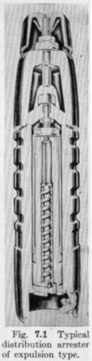
A typical expulsion arrester for the protection of distribution apparatus
is illustrated by Fig. 7.1. [...]

In Fig. 7.1, the characteristic element or interrupter is a fiber tube inside
of which is a rod on which is cut a deep spiral groove. [...]
The series gap is an integral part of the arrester. It is shown at the top,
in Fig. 7.1, visible through the window in the bell-shaped porcelain. The
connection to the line conductor of the system is made at the top, the ground
connection to the terminal on the bottom.
The arrester shown in Fig. 7.1 is a typical one. There are numerous constructions
of expulsion arresters in successful use on distribution circuits. The greatest
number of these have been supplied as integral parts of self-protecting transformers,
such as the 'CSP' transformer illustrated in Fig. 7.8.
There are several constructions of valve-type distribution arresters. Such
arresters consist of a series spark gap and a valve element enclosed in a
porcelain or glass housing. [...] The valve elements of all but one of the
commercial distribution valve arresters consist of small crystals of silicon
carbide, either bonded together or held in compression. The exception has
a characteristic element made of small pellets of one of the oxides of lead.
It is appropriately known as the pellet arrester.
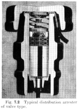
A cross section of a typical valve arrester is shown in Fig. 7.2. The physical
differences between it and the expulsion arrester are apparent from a comparison
of Figs. 7.1 and 7.2. The valve arrester is completely enclosed. The series
gap at the top consists of one or more short gaps between relatively flat
electrodes. The valve element in the arrester shown is a cylindrical block,
formed under considerable pressure, of silicon carbide and a binding material.
Usually these arresters have line and ground leads by which they are connected
to the current, although some constructions have clamp-type terminals.

[...] The expulsion arrester has been in use in various forms since about
1931. [...]
Station- and Line-type Lightning Arresters for Power Apparatus
The designations station- and line-type arrester have been in current use
for many years to identify two classes of arresters and arrester performance.
[...] Both are used in stations. 'Line-type' does not connote the protection
of lines, but the phrase was orginally coined to describe an arrester smaller
and less efficient than the station type, for economical use in small substations
'out on the line', as distinguished from large stations. A more descriptive
nomenclature would be to call the station-type arrester a 'heavy-duty station
arrester', and to designate the line type a 'light-duty station arrester.
[...]
Station-type arresters are larger and more costly, they have greater surge-current
withstand strength and better protective characteristics, and are used on
higher-voltage systems. [...]
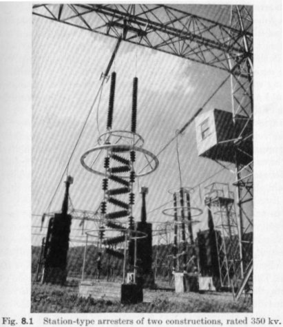
Arresters with ratings of 350 kv, Fig. 8.1, have been built and installed
on an experimental line which is energized for test purposes at voltages as
high as 500 kv.

The line-type arresters are, as a matter of fact, small editions of the station
types; they are lower in cost, with not so good protective characteristics
as the station type, and less capacity for surge current. The station-type
arresters are used where the highest degree of protection is desired, such
as on large transformer banks or in large substations. The line-type arresters
are generally used to protect smaller substations or transformers where the
user considers the expense of station arresters not warranted.
Station and line arresters are of the valve type. Expulsion arresters are
not recommended for the protection of apparatus operating at voltages higher
than 15 kv. [...]
Station- and line-type arresters are, in principle, the same as the distribution-type
valve arresters described. [...]
In construction, station- and line-type arresters are similar except in size.
The valve elements of line arresters are smaller in diameter and volume than
those of station arresters. This results in smaller outside diameter and lighter
weight. It is accompanied by higher voltages during discharge and lower surge-current
withstand ability. Station-type arresters have greater margins of protection
and are practically immune to damage by lightning. Very few cases are known
where modern station arresters have been damaged by lightning alone. [...]
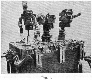
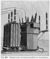
To the best of the author's knowledge, there has been no case of insulation
failure caused by surge voltage to a modern transformer protected by station-type
lightning arresters of current design mounted on the transformer as in Fig.
8.4.
[...] Both the station- and line-type arresters are built in units of certain
definite ratings. Each unit is in itself a complete arrester, and may be used
as such. Arresters of ratings higher than the largest available single one
are built up of two or more units stacked in series. One manufacturer of station-type
arresters makes units rated 3, 6, 9, and 12 kv. Higher-rated arresters consist
of multiples of these units, preferably of the 12-kv unit. Thus, a 15-kv arrester
would consist of a 12- and a 3-kv unit in series. A 121-kv arrester consists
of ten 12-kv units in series. Another manufacturer makes units rated 3, 6,
9, 12, 15, 20, 25, 30, and 37 kv. For any standard ratings up to and including
37 kv, the proper single unit is used. For higher ratings, multiples of units
are stacked in series. Thus, a 73-kv arrester consists of two 37-kv units,
and a 121-kv arrester consists of two 25-kv and two 37-kv units.
The unit construction has several advantages over the formerly used tailor-made
arresters, both to the manufacturer and to the user. It simplifies the manufacturing
and stocking, which keeps down costs and prices. It speeds up deliveries.
It simplifies erection and facilitates the user's stocking and ordering problems.
If testing is to be done, it facilitates the test procedures. It also facilitates
the changing of ratings in the field if there is a change in system voltage
or a change in system grounding or if arresters are moved about.
All manufacturers of line-type arresters build units rated 20, 25, 30, and
37 kv. In some cases, units rated less than 20 kv have been used.
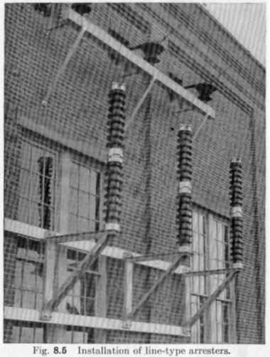
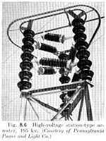
Typical arrester installations of both types are illustrated in Figs. 8.4
and 8.5. Station-type arresters up to and including 121 kv of rating stand
by themselves without any mechanical bracing. Above these ratings, arresters
may be built in several ways. The arrester may be a straight column of units
supported on a foundation. In such a case, 145-kv arresters and larger require
mechanical bracing, because heavy wind pressures may produce moments at the
bottom of the column that exceed the cantiliver strength of the porcelain
housing and hardware. This support should be at the top of the arrester, in
order not to disturb the electrostatic field around the series gaps of the
arrester.

Another construction which has found favor for high-voltage arresters is
the suspended arrester shown in the foreground of Fig. 8.1. The arrester units
are hung between strings of suspension insulators supported from steel work.
When steel to support the arrester is available, this is a compact construction,
easy to erect. Suspended arresters of this general type have been used widely
in regions where earthquakes occur, because the design is a loose-jointed
one that will give when forces are applied to it.
The three-legged structure in the right background of Fig. 8.1 is another
construction. It is a self-supporting structure in which certain of the porcelain
sections are insulators, and others arresters. The arrester units are connected
together by the steel pipes shown between the three legs. Another self-supporting
construction of high-voltage arrester is shown in Fig. 8.6.
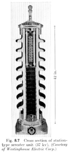
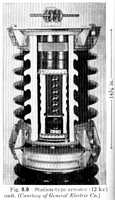
Figures 8.7 and 8.8 show representative station-type units. The operating
elements are enclosed in porcelain weather casings. To these are attached
metal end fittings for mounting and assembly purposes. The series gap elements
are usually enclosed in a separate porcelain tube which is tightly sealed,
to exclude any possibility of moisture accumulating in the gaps. [...]

The valve elements are usually made in the form of cylindrical blocks or
discs. Their number increases with the arrester rating. The number of series
gap elements also increases with the voltage rating. The valve blocks are
made of amixture of crystals of silicon carbide and a suitable binder. They
are formed in molds under high pressure, then baked or fired. The ends are
covered with a metallic coating to provide good electrical contact, and the
sides are coated with an insulating material to prevent surface flashovers.
[...]
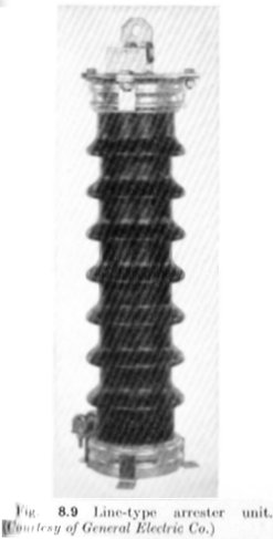
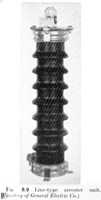
Line-type arrester units are basically similar to the station-type arresters.
The series gaps again consist of a number of short gaps separated by high-resistance
spacers. The valve blocks are made of material similar to those used in the
station arresters, but they are smaller in diameter. Because of the smaller
cross section of the elements, the entire arrester unit is of less diameter
and less weight than the station type, with attendant lower cost and less
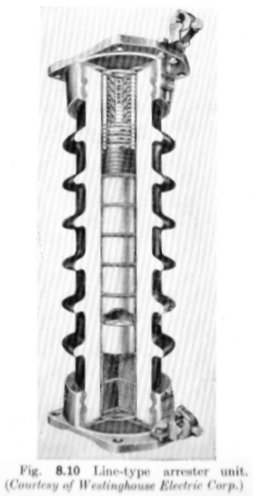
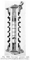
protective efficiency. Representative line-type arresters are shown in Figs.
8.9 and 8.10.
[...]
What Does an Arrester Fear?
[...] There are, in general, four possible causes of damage to lightning
arresters in service. They are lightning of great severity, a power frequency
or sustained voltage in excess of the arrester rating, mishandling in service,
or a defect in the arrester. [...]
Examples of maltreatment are hosing high-voltage arresters while energized,
which may depress the 60-cycle sparkover considerably; omitting mechanical
bracing from arresters that require it; not observing the manufacturer's recommendations
for clearances; installation of sea-level arresters at high altitudes; or
of standard constructions in very dirty or wet surroundings. [...]
The principal cause of damage to arresters in the field is a system-voltage
condition that subjects the arrester to a power frequency or sustained voltage
in excess of its voltage rating. In many cases, the conditions that are dangerous
to lightning arresters are conditions that are not good for the system as
a whole, for reasons other than the hazard to arresters. Some arrester failures
have disclosed conditions that were not known to exist, and have led to improvement
in system operation. [...]
Location and Application of Lightning Arresters
[...] In stations that are not shielded and whose incoming lines are also
not shielded, the best practice is to locate the arresters as close as possible
to the transformer because, in such stations, the likelihood of steep front
surges is real. This protects the transformer. The risk of trouble on switching
equipment must then be run if economics prevent the installation of arresters
there also. This is usually not so serious as it may appear. Oil-filled breakers
and disconnecting switches are so built that the internal impulse insulation
strength or the flashover distance over open switches is greater than that
to ground from the terminal. Thus, a surge in excess of the insulation strength
is likely to flash to ground without damaging the apparatus. This may cause
an outage, but the probability of this may be small and the risk warranted.
[...] In some cases, valve arresters have been installed at the transformers,
and transmission-line-type expulsion arresters at the line entrances, even
though those arresters may not give complete protection against all surges.
In shielded stations with shielded incoming lines, conditions are somewhat
different, because the shielding reduces the probability of steep and high
surges. Most high-voltage stations and lines are shielded, and the practice
of shielding is being extended to 34.5- and 23-kv systems. The medium- and
lower-voltage substations are often not of great extent, and trouble-free
service may be experienced with station-type arresters located only at the
transformer. [...]
Protection for Secondary and Other Low-Voltage Circuits
Secondary circuits have been defined as those circuits which distribute power
to the machines or devices or appliances that utilize it, such as lights,
modors, and radios. These circuits are usually 120/240, 440, 550, or in some
cases 660 volts. In this chapter will be considered circuits operating at
less than 750 volts. They may be single- or three-phase. The 440 and higher
voltage circuits are usually three-phase. There are also coming into increasing
use, 208-volt three-phase circuits for three-phase power, giving 120 volts
to neutral for lighting. The power for secondary circuits is usually obtained
from a step-down transformer fed from a distribution system.
Dwellings are almost universally supplised by 120-volt two-wire or 120/240-volt
three-wire single-phase circuits with the neutral wire grounded in the consumer's
premises and, frequently, also at the distribution transformer. [...] If the
secondary circuits to the user's premises are overhead and long, say 500 feet
or more, they will very likely pick up lightning voltages by induction and
sometimes may be struck. Also, surge voltages may enter the secondary circuits
from the primary by way of the transformer, whether the transformer has protection
on the primary or not. Since the insulation in the customer's premises - for
example, switches, outlets, appliances, and in parts of the watthour meter
- is relatively low, some flashovers and punctures may occur. These will be
infrequent unless the secondary is highly exposed. Because flashovers and
punctures are infrequent and rarely cause permanent damage, the house circuits
are usually not protected against lightning. In a house, there are many air
gaps with low flashover in the circuits, such as in outlets, lamp sockets,
and in the meter. The flashover voltage of these may be of the order of 4,000
to 6,000 volts only. This will protect most of the solid insulation. The voltage
to ground or neutral being only 120 and the short-circuit currents usually
being limited in magnitude, an arc will seldom be sustained. It is not unusual
to hear a spark jump in an outlet when a stroke hits nearby. Repeated flashovers
in the same place will eventually cause carbonization of the insulation and
a permanent short and blown fure or open breaker and replacement of the damaged
part. [...]
Occasionally, watthour meters are damaged by lightning. The cost of an adequate
arrester is an appreciable part of the cost of a meter, and, as a result of
this, it is apparently not economical to protect all meters on a system. It
is more practical to gamble on the low probability of a meter being damaged,
and to replace a meter if it is damaged. Where damage is frequent in certain
locations, arrester protection should be applied. [...]
There are numerous overhead 440-volt circuits that feed power to various
utilization points; for example, in the oil fields. There are also some that
supply power to railway signals. They may be of considerable extent. Usually
they are on wood poles, therefore highly insulated and capable of sustaining
quite high lightning voltages. Such circuits should be treated as distribution
circuits, and the static equipment connected to them should have protection
as used on distribution transformers. [...]
Railway signal systems involve a number of circuits, operating at different
voltages. Those that operate the signals are low voltage, either alternating
or direct current, obtained from batteries that are usually kept charged by
rectifiers. They are controlled by relays which, in the conventional block
signal or track circuit systems, are actuated by voltage or lack of voltage
between the rails. There may also be relay circuits that run for some distance
over poles, and in the CTC, or centralized traffic-control system, there may
be long circuits to a central control station. Power for the circuits and
for battery charging is supplied from a transformer located usually in the
relay house or box. This, in turn, is fed from the secondary of a transformer
on a pole, like a distribution transformer, except that the secondary voltage
is usually 115 volts and the secondary is not grounded. The pole-top transformer
is energized from a transmission line operating at one of the preferred voltages
from 440 to 13,800. A common voltage for long signal power-transmission lines
of 30- to 40- mile sections is 4,600 volts. These lines are usually single-phase
ungrounded. Occasionally three-phase lines are used.
All these circuits may be subject to lightning voltages. Lightning damage
to a relay or the failure of power as the result of a lightning disturbance
may stop trains unnecessarily and interfere with traffic. The signals are
the nerve system of the railroad, and lightning protection is used throughout
it to keep it in working order. [...]
If there are long signaling lines exposed to induction from paralleling a-c
power lines or trolleys, the probabilities of high voltage being induced during
faults on the paralleling power lines should be evaluated and lines treated
accordingly. [...]
This information comes from
- Lewis, Walter Wallace (Former Transmission Engineer for Central Station
Engineering Division, General Electric Company). The Protection Of Transmission
Systems Against Lightning. New York, NY: John Wiley & Sons, Inc.
Copyright 1950. LOC TK3248.L4.
The 'Preface' states:
The literature on the subject of lightning is voluminous. In 1937, the American
Institute of Electrical Engineers issued the Lightning Reference Book,
comprising about 1500 pages the size of the Transactions and containing
about half the available papers which appeared in American technical periodicals
between the years 1918 and 1935. An index of a similar-size volume of papers
published from 1936 to 1949 is now in preparation. There has long been need
for a book in which the most important information on lightning is assembled
and applied in a practical way to the design and protection of transmission
lines and stations. That is the purpose of the present book. [...] It is believed
that the book will appeal to operating men and engineers of power utilities,
men in the manufacturing companies who deal with power systems, people interested
in atmospheric electricity, and teachers and students of power courses in
college, both graduate and undergraduate. In writing the book, I have drawn
on my own experience of about 25 years in lightning investigation, as recorded
in the group of papers of which I am author or coauthor, and have also drawn
heavily on the experience and finding of others as recorded in numerous papers.
[...]
The following information is excerpted from this book.
Introduction
Engineers and operating men of electric power utilities appreciate the part
that lightning plays in the design and operation of their systesm. In territory
where lightning is prevalent, it is probably the most usual cause of outages
and damage.
In 1924, I had occasion to investigate the failure of a transformer on a
power system in Pennsylvania, and found that there were no lightning arresters,
that the transmission line had no overhead ground wires, and futhermore that
it had very high insulation compared with that of the transformer. [...]
The first two 220-kv lines had been in operation in California for a year
or two, and there were plans for one in the East.
In 1926, the Wallenpaupack-Siegfried 220-kv line in northeastern Pennsylvania
was put into operation without overhead ground wires and without lightning
arresters at the terminals. A cooperative lightning investigation was begun
with a small number of surge-voltage recorders. From April to August, the
line operated at 220 kv; then lightning came along and broke down some of
the transformers, necessitating changing over to 66 kv. Next year, the investigation
was enlarged and spread to other systems: the Ohio Power Company, the Consumers
Power Company, the New England Power Company, the Alabama Power Company, the
New York Power and Light Company, and a number of Electric Bond and Share
Company affiliates. [...]
In 1930 the first, and so far as I know the only, oscillogram of the voltage
due to a direct stroke ws obtained at Cherry Valley on the Wallenpaupack-Siegfried
line. [...]
The investigation practically ceased during World War II, except that it
was kept going on a minor scale on the Consumers Power Company system in Michigan,
and on the Appalachian Electric Power Company system in Virginia. The Consumers
Power Company, Appalachian Power Company, and Ohio Power Company investigations
are still going on in 1949 to clear up a few details, and the Empire State
Building investigation has been resumed. [...]
Voltage Caused by Lightning and Switching
[...] During the years 1925 to 1930, investigations were carried out on numerous
power systems in all voltage classes, by means of the klyndonograph and surge-voltage
recorder.
The instruments were coupled to the line by means of capacitance potentiometers
or voltage dividers, formed either by two sets of pipes supported on insulators,
one set at line potential and one set near ground potential, or by two sets
of rings supported on insulator strings. One arrangement is shown in Fig.
3.14 (a). The bottom ring is supported by special hardware between the second
and third insulator units, the hardware of the unit above the supporting unit
also being grounded. The recorder is connected between the bottom ring and
ground.
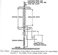
[...] The number of insulators N is above the grounded unit is changed for
various line voltages, as shown in Table 3.1, giving the voltage divider ratios
indicated. A view of a field installation on a 220-kv line is shown in Fig.
3.14 (b). Here there are nineteen insulator units above the bottom ring and
one below it. The voltage ratio is approximately 80 to 1. The metal box at
the top of the wood pole contains the surge voltage recorder.
Table 3.1 - Insulator String
Voltage Divider Ratios |
Rating
of Line,
kv, Phase
to Phase |
Number of
Insulator
Units, N |
Voltage
Divider
Ratio |
33 |
3 |
15 |
44 |
5 |
20 |
66 |
7 |
26 |
88 |
10 |
36 |
110 |
12 |
45 |
132 |
14 |
60 |
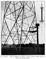
For lower-voltage lines, various combinations of suspension insulator or
bus type insulator units have been used, sometimes with and sometimes without
auxiliary metal rings or discs, depending on whether the installation was
indoors or outdoors. [...] Figure 3.15 (a) is a diagram of a potentiometer
arrangement for 13.2 kv by using standard suspension insulators, and Fig.
3.15 (b) an alternative arrangement using bus insulators. Both arrangements
are for indoor use, and have an approximate ratio of 5 to 1.
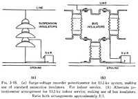
[...]
Shielding by Overhead Ground Wires and Masts
On highly insulated lines without overhead ground wires, the lightning voltage
could build up to enormous values. Voltages of 4500 and 5000 kv were recorded
on a 132-kv wood-pole line, and approximately 3000 kv on a 220-kv steel-tower
line. The voltage depends on the current involved and the impedance of the
circuit through which the current travels, and the insulation flashover depends
on the steepness of the voltage wave. If the conductor is struck, a comparatively
small current acting through the conductor surge impedance will build up a
voltage that will flash over the line insulation. For example, 7500 amperes
acting through 400 ohms surge impedance will build up the 3,000,000 volts
recorded on the 220-kv line.
If the line is equipped with overhead ground wires, and a ground wire is
struck, then the impedance through which the current acts is very much reduced,
and a corespondingly higher current is required to cause flashover. If the
impedance is reduced to say 25 ohms, then approximately 120,000 amperes would
be required to produce the same 3,000,000 volts.
The overhead ground wire performs two main functions: It intercepts the direct
stroke, keeping it off the conductor; and it distributes the current in two
or more paths and thereby reduces the voltage drop. If the ground wire is
struck in midspan, current divides and flows toward both towers, and at the
tower the current divides again between the tower and the outgoing ground
wire. If the tower is struck and there is one overhead ground wire, the current
divides into three paths, one in the tower and two in the branches of the
ground wire. A third function of the overhead ground wire, of a minor nature,
is to reduce voltage induced on the conductors from nearby strokes. [...]
When a lightning stroke builds up from a tower top with no ground wire present,
the entire current feeding into the extending streamer tip, proceeding at
approximately 150 feet to 200 feet per microsecond, flows from the ground
into the tower base and up through the tower structure. [...]
A voltage instantaneously equal to stroke current times tower footing resistance
builds up across each insulator assembly. This potential, combined with the
normal excitation voltage of each conductor, gives the total insulator assembly
stress. [...] One assembly flashover reduces the tower potential just as much
as connecting one-half the conductor surge impedance across the tower footing
resistance would. This reduction in tower potential may be sufficient to prevent
other insulator assemblies flashing over, and if so, only a single-phase flashover
is obtained. It the stroke current, however, is sufficiently high again to
increase the tower potential in spite of the lowered impedance to ground,
additional assemblies will flash over. Insulator flashover may occur at adjacent
towers if the potential carried along the flashed conductors is sufficiently
high. A specimen field record of such an occurrence [was] obtained on the
Wallenpaupack-Siegfried 220-kv line with horizontal conductors (Fig. 6.15)
during the season 1933.
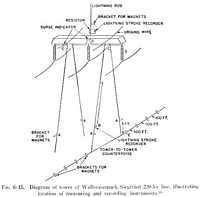
[...] A direct stroke to a tower of a line equipped with overhead ground
wires is very much the same as without ground wires, especially when tower
footing resistances are low. The current flowing into the stroke feeds in
through the ground wire from both directions as well as up through the tower
structure. As a result, the resistance voltage drop at the tower footing is
reduced in proportion to this decrease in tower footing current. [...]
A specimen field record [was] obtained during 1934 from the Glenlyn-Roanoke
132-kv double-circuit line (Fig. 6.16) pertaining to this case.

[...] If the outermost conductors are the top conductors, then the ground
wires would be moved outward and possibly upward, in order to avoid having
the ground wires and conductors come together in case the wires were loaded
with snow or ice and the lower one unloaded and swung upward.
On the basis of these principles, Schwaiger shows the protective zones of
one, two, and three overhead ground wires, as in Fig. 6.22.
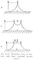
[...] On the basis of a study of operating experience, Lewis proposed the
following criteria for the location of overhead ground wires: On double-circuit
lines with conductors vertically arranged, two ground wires, one over each
outermost conductor, usually the middle conductors, and in a plane above the
plane of the top conductors a distance equal to the vertical spacing between
conductors. On single-circuit lines with conductors arranged horizontally,
two ground wires in a plane above the plane of the conductors at a height
equal to two-thirds the spacing between conductors and a distance apart equal
to the spacing between conductors, that is, above the tower legs or above
the poles in a wood H-frame arrangement (Fig. 6.23).
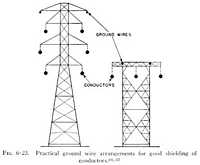
[...] Another interesting comparison is afforded by the 230-kv line of the
Metropolitan Water District of Southern California. This line extends from
Hoover Dam to Hayfield and Parker Dam, a distance of about 237 miles. The
3 conductors are spaced horizontally 22.3 feet, and insulated with 13 discs
spaced 5 3/4 inches. The line was placed inservice in November 1938 without
overhead ground wires. During the 4 years from 1939 to 1942 inclusive, system
outages due to lightning totalled 118, an average of about 29 per year. In
1943, two half-inch steel overhead ground wires were added on brackets extending
upward from the tower bridge. The ground wires are approximately 32 feet apart,
and are 16.5 feet above the conductors. In the 6 years from 1943 to 1948 inclusive,
only 3 system outages due to lightning have been experienced, an average of
0.5 per year.
THe Philadelphia-Chester 14.1-mile 66-kv line operated from 1917 until 1932
before having its first tripout. At this time, a flashover took place at a
tower having a footing resistance of 2.5 ohms, which tripped the lineout.
A second flashover took place in 1937 at a tower having a footing resistance
of 20 ohms. No additional tripouts had taken place up to the end of 1947.
Thus there wer eonly 2 tripouts in 30 years, an averageof 0.47 tripouts per
100 miles per year.
In 1935, a stroke took place to tower 16 on this line, with an indicated
tower current of 132,000 amperes. However, no flashover was associated with
this occurrence.
This line is double circuit, with the two circuits in vertical arrangement.
The vertical distance between conductors is 7.5 feet, with two ground wires
7 2/3 feet above the top conductors at the tower. The middle-phase wires are
offset 2.5 feet beyond the top and bottom wires, making them 16 feet apart.
The overhead ground wires are also 16 feet apart, and directly over the middle
conductors.
At suspension towers, the conductors are insulated with 8 discs spaced 5
inches apart, having a flashover on the positive 1.5 x 40 wave of approximately
700 kv. The average span length of the line is 480 feet, and the tower footing
resistance is naturally low, probably in most cases under 5 ohms. [...]
Zubair analyzed the performance of the Victoria Falls and Transvaal Power
Company's 63.5-mile, 132-kv line. The line is double circuit with 12 feet
of vertical spacing between conductors, and a horizontal distance between
the circuits of 23 feet. There is one ground wire about 13.9 feet above the
plane of the top conductors. The prevailing insulation is 9 discs, having
a dry 60-cycle flashover of 350 kv runs. [...]
Insulation and Spacing of Conductors
[...] Basic impulse insulation levels have been set up for apparatus, and
practically all apparatus such as transformers, circuit-breakers, and disconnecting
switches receive a withstand test equal to this value (Table 8.1).
The highest system voltage at present in use is 287 kv, but the Joint Committee
on Coordination of Insulation visualized 345 kv as the next step, and included
this value in Table 8.1. More recently, the Joint EEI-NEMA Committee on Preferred
Voltage Ratings for A-C Systems and Equipment has been giving consideration
to 360 kv as an alternative, so data on this value have been included in Table
8.1 and subsequent tables.
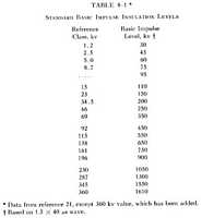
[...] Table 8.2 allows ready conversion of 10-inch-diameter insulators from
4 3/4 and 5 1/8 inch spacings, to 5 3/4 inch spacing.

[...] In Table 8.8, column 2, are given for the standard insulation classes
the number of insulator discs, spaced 5 3/4 inches apart, whose wet 60-cycle
flashover will equal or exceed 3.5 times line-to-neutral voltage. This is
the smallest number of insulators which will have an impulse flashover equal
to or greater than the basic impulse insulation level.
Also given in Table 8.8 are the numbers of discs whose wet 60-cycle flashover
will equal or exceed 4, 4.5, and 5 times the line-to-neutral voltage. In column
6, for comparison, are given the numbers of discs representing average practice.

[...] With each level of insulation, there is a proper spacing between conductors
and to the steel structure, to develop the full strength of the insulator
string selected. Let us take the minimum spacing to the steel structure A
(Figs. 8.6 and 8.7) as a spacing that will have an impulse flashover 10 per
cent greater than the impulse flashover of the insulator string.
Spacing B (Figs. 8.6 and 8.7), the horizontal distance from conductor to
tower when the conductor is hanging vertically, will be such that when the
conductor is swung to 30 degrees from the vertical, the impulse flashover
from conductor to tower (spacing A) will be 10 per cent greater than the insulator
string flashover. It is assumed that during the summer season, when lightning
prevails and there is no ice or snow, 30 degrees is ample to consider for
the conductor swing.
When spacing B from conductor to tower has been determined, spacing D between
conductors for the horizontal arrangement (Fig. 8.6) becomes 2 times spacing
B, plus the width of the tower legs.
For the vertical arrangement (Fig. 8.7), the spacing between horizontal planes
through the conductors, spacing C, is a minimum of 2 times spacing A, since
the insulator string itself has a length approximately equal to spacing A.
On the tower illustrated in Fig. 8.7, on account of the slope of the crossarm
bracing, the spacing between conductor planes naturally will be somewhat greater
than 2A. In other types of towers without crossarm bracing, this may not be
the case, and the minimum spacing 2A can be used.
It was found that in order fully to shield the conductors from direct strokes,
two overhead ground wires are desirable, for either horizontal or vertical
arrangements of conductors. If the two ground wires are placed close together,
they blanket each other and the full benefit of the two wires is not secured.
[...]
For a single-circuit line of the usual design, with the conductors horizontally
arranged (Fig. 8.6), it works out well mechanically to place the ground wires
above the tower legs or above the poles in a wooden H-frame arrangement; that
is, on a vertical plane about midway between the two conductors. Frequently
in practice the ground wires are supported on brackets extending upward from
the tower bridge.
In the double-circuit vertical arrangement (Fig. 8.7), the ground wires are
well coupled with the top conductors, but are more remote from the middle
and especially the bottom conductors, so that the coupling factor is rather
low. To offset this loss of coupling factor, the ground wires should be spread
further apart. A good position in practice has been found to be about directly
above the outermost conductors, which are usually the middle conductors.
The ground wires should be high enough above the conductors to avoid flashover
between conductors and ground wires at midspan. However, if the ground wires
are too high, the coupling with the conductors will be small, and if the tower
voltages is raised above ground by lightning current in the tower, the voltage
across the insulator string will be greater than it would have been with the
ground wires closer to the conductors.
It has been found by experience that a height of approximately two-thirds
the spacing between conductors for the vertical arrangement is about right
to give good coupling to the conductors, and at the same time avoid midspan
flashover. Spacing C = 2A follows these criteria (Table 8.10).
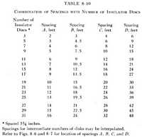
In regions where snow, ice, or sleet is likely to accumulate on the conductors,
it happens occasionally on vertical arrangements (Fig. 8.7) that the bottom
conductor unloads its snow and ice and swings up level with or above the middle
conductor. Also, in case of a coating of ice or sleet and a light wind in
the proper direction, dancing or galloping sometimes occurs, the conductor
swinging in an elliptical loop, with the longer axis of the loop vertical.
Lightning is not likely to be present under these conditions. Nevertheless,
the spacing between conductors when in their closest position should be amply
safe, so that the dynamic voltage or overvoltages will not cause flashover.
[...]
The impulse flashover of two insulator discs 10 inches in diameter and spaced
5 3/4 inches apart is approximately equal to the flashover of 12 inches of
standard rod gap, and this relation holds roughly for multiples of two discs
and 12 inches of rod gap. This fortunate relationship enables us to write
an equation between the number of insulator discs of this size and spacing
A as given in Table 8.10:
Spacing A (feet) = ( Number of discs + 1 ) / 2
Then
- Spacing B equals 1.5A
- Spacing C equals 2A
- Spacing D equals 3A
- Spacing E equals 0.5A to 1.5A.
Thus, all the important conductor and conductor-to-tower spacings may be
found from the number of insulator discs by a simple mental calculation. [...]
Table 8.11 gives flashover values of pin type insulators from the catalogs
of two manufacturers. [...] Pin type insulators are commonly used on lines
up to and including 33 kv, and sometimes at 44 and 66 kv. Their selection
for a particular line is based not only on flashover voltage, but also on
ability to retain their flashover value in regions where the surface of the
insulator may become contaminated by exposure to dust, chemical fumes, salt
spray, etc. The same observation applies, of course, to some extent to the
selection of suspension insulators.
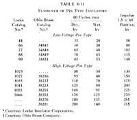
On lines with pin type insulators, there will be no swing of the conductors
at the structure, so that spacing A could be used between conductor and down-lead
as far as the elctric clearances are concerned. However, mechanical considerations
may call for larger spacing, and spacing B would be applicable. [...]
On account of the possibility of wood poles and crossarms splitting from
the lightning flashover, it is desirable to have the flashover go from the
conductor to the down-lead through air, rather than via the insulator string
and crossarm or pole. If the impulse flashover through air is made about the
same as the insulator flashover, the added insulation of wood in series with
the insulator will ensure that flashover will take place through air to the
down-lead. In the higher voltages, it is very common to build wood-pole lines
of the H-frame arrangement, with two overhead ground wires and ground leads
down the poles (Fig. 8.22).
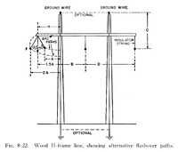
[...] An expident to increase the length of wood in series with the porcelain
is illustrated in Fig. 8.23. Here the down-lead is tapped off the ground wire
a few feet away from the pole, and the lead swings down and contacts the pole
some distance below the crossarm.
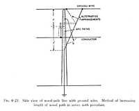
[...] Andrews had the idea that sufficient wood and air insulation could
be introduced, so that even if lightning glashover took place, power frequency
would not follow. His standard 33-kv line consutrction consisted of wood poles
with a 10-foot wood crossarm supported by a steel angle iron brace. Two conductors
were mounted on one side of the pole, and one conductor on the other. This
design he modified by dropping down the crossarm and placing one insulator
on the ridge of the pole, approximately 5 3/4 feet above the crossarm. The
other two conductors were supported by insulators at the ends of the 10-foot
crossarm. Wood crossarm braces were used, and wood insulators in guy wires
( Fig. 8.24(a) ). Where there was not sufficient space on the pole to permit
lowering the crossarm, one conductor was mounted on top of the pole, and wood
crossarm braces were installed ( Fig. 8.24(b) ).
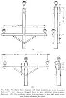
A marked improvement in the number of flashovers was noted in 9 months' operation
on a small length of line with the improved insulation, but there was about
the same percentage of pole and crossarm damage as with the original design.
Andrews and McCain reported for a 3-year period on 4 lines similar to those
described ( Fig. 8.25(a) ), but including some corner poles with porcelain
guy insulators and minimum wood insulation ( Fig. 8.25(b) ). Thirteen per
cent of the standard poles without guy wires which flashed over showed power
follow-up; also, 42 per cent of the standard poles with insulated guys; and
90 per cent of the corner poles. Tripouts varied from 13 to 80 per 100 miles
per year, with an average of 31 per 100 miles per year.
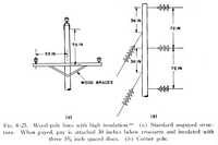
[...] The strength of wood in series with the porcelain insulators may be
evaluated at about 50 kv per foot on an impulse basis, or one-half disc insulator
for each foot of wood. This should be compared with the strength of air gaps,
in which 1 foot of air gap is equivalent to approximately two insulator discs.
[...]
Alternative Methods of Protecting Transmission Lines
A large number of existing lines have been built without overhead ground
wires or means for retucing the footing resistance, such as driven rods or
counterpoise wires. New lines will continue to be built in this manner where
the design adopted does not lend itself to the installation of overhead ground
wires, where the line is not sufficiently important to justify the expense
of overhead ground wires, where duplicate lines seem to assure adequate service,
or for other reasons.
Alternative methods of affording a certain degree of protection to these
lines are available; among these are protector tubes, ground-fault neutralizers,
and automatic reclosing.
Protector tubes are sometimes called "expulsion protector tubes",
"expulsion protective gaps", "de-ion tubes", and "line
type expulsion arresters". The essential elements of such a tube are
illustrated in Fig. 9.1.
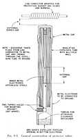
[...] Various ways of mounting protector tubes on lines are shown in Figs.
9.2, 9.3, and 9.4.

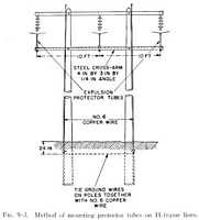

[...] Wisco and Monteith report the experience on a 54-mile, 66-kv, single-circuit,
steel-tower line of the Interstate Power Company. The line was equipped with
four insulator discs and no overhead ground wires. In 6 years' operation before
protector tubes were installed, the outages averaged 46.1 per year. Protector
tubes were mounted on a light steel crossarm beneath the horizontal conductors.
In the following 6 years, theoutages were reduced to an average of 3.1 per
year, a reduction of about 93 per cent. [...]
The suggested arrangement for a double-circuit line is shown in Fig. 9.10.
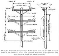
[...] River-crossing towers are often high and the spans long, making it
difficult and expensive to support overhead ground wires. Even if ground wires
were present, a direct stroke to one of the crossing towers might result in
sufficient resistance drop in the tower to flash over the insulators. The
ground wires have therefore in some cases been omitted, and protector tubes
successfully relied on to prevent insulator flashover at the two ends of the
span. Lightning arresters have also been used for the purpose.
The ground fault neutralizer, also known as the Petersen coil, was devised
by Dr. W. Petersen. The ground-fault neutralizer, in its most common form,
is a reactance coil placed between neutral and ground and specially proportioned
in relation to the charging current of the system. In case of a ground fault
on the system, a current flows through the coil which is substantially equal
to and 180 degrees out of phase from the ground-fault current, thereby neutralizing
the ground-fault current. Another form, not so commonly used, consists of
a Y-delta transformer bank with the Y winding connected to the three phases
of the system to be protected and its neutral grounded; it has an adjustable
reactor connected in a corner of the delta, the delta being otherwise unloaded.
On account of the prevalent use of the isolated neutral system in Europe,
the Petersen coil found ready acceptance as a means of improving the service
of lines of all voltages from 5000 to 220,000 volts. In this country, the
solidly grounded neutral system has become firmly established, and therefore
the neutralizer and other grounding devices have not received such wide acceptance.
Nevertheless, the neutralizer has a distinct application on certain types
of systems, and its use has been gradually increasing. Neutralizers have been
installed in this country on systems ranging from 2.4 to 230 kv. [...]
Figure 9.13 shows an interior view of a ground-fault neutralizer with a built-in
shunting resistor, for a 100-kv system. Figure 9.14 shows an exterior view
of a neutralizer for a 140-kv system with an early remote-control tap-changing
mechanism. Figures 9.15 and 9.16 show interior and exterior views respectively
of a modern neutralizer for a 34.5-kv system, with external lightning arrester
and with an electrically operated tap-changing switch. Figure 9.17 shows an
adjustable coil neutralizer of 4 to 1 reactance ratio for a 6600-volt system.
Figure 9.18 is a view of the disconnecting and by-pass switches and their
control mechanism.
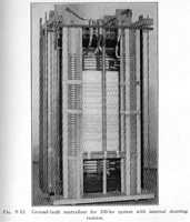
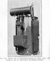

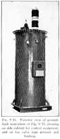


[...] Entering into the calculations of the capacitance to ground are the
height of the conductors above ground, the spacing and size of conductors,
and the spacing and size of ground wires, if any. It is generally assumed
that the grue ground plane is at the ground surface, although this is not
at all certain, especially if the currents involved are large. The height
above ground is usually assumed as the height of the tower, but it may be
less in the span or at times considerably greater, as when crossing gulleys
and valleys. An accurate calculation would require that the line profile be
planimetered. If corona is present, the apparent conductor size is increased
and the capacitance becomes somewhat larger than called for by the actual
conductor size. If the line is on a right of way bordered by trees, the presence
of these trees may change the capacitance to ground, especially when it is
raining. [...]
The Public Service Company of Colorado installed a combination grounding
transformer and ground-fault neutralizer in 1944 on their 13.8-kv system in
Denver. The system consisted of about 400 miles of overhead line and about
8 miles of underground cable, or the equivalent of about 630 miles of overhead
line. THe coil was rated 122 to 263 ohms and 61.3 to 29.4 amperes. A second
duplicate coil was installed in 1947.
The record of these neutralizers shows operations for the 4 years from 1944
to 1947 inclusive as follows: 914, 886, 963, and 770.
In 1946, of the 963 operations, 55 per cent were associated with bad weather
and 45 per cent with foreign objects, equipment failures, or unknown causes.
No feeder outages were associated with 83 per cent of the total operations,
but feeder outages were associated with the remaining 17 per cent, resulting
in 48 tripouts and 4 lockouts. [...]
Before the installation of the coils, faults on one part of the system caused
secondary faults on other and remote parts of the system. Installation of
the coils has stopped these occurrences.
The Metropolitan Edison Company installed three ground-fault neutralizers
on their 66-kv system in 1937. On tuning the coils, each with its proper proportion
of the system, the coil current was found excessively high without fault on
the system, in some cases far exceeding the continuous rating of the coils
(about 30 per cent of full current rating). Certain lines were wholly or partly
transposed, so that the coil currents were reduced to a point considered acceptable.
On the lines of fairly modern construction, with ample insulation and clearance,
the improvement was marked, the first year's operations showing a reduction
of 88 per cent in interruptions as compared with the previous 5 years. The
older lines with pin type insulators and small clearances showed about a 30
per cent reduction.
In 1939, three ground-fault neutralizers (Fig. 9.26) were placed in service
on the 230-kv Boulder Dam-Barre-Chino line of the Southern California Edison
Company, consisting of 234 miles from Boulder to Chino, and 26 miles from
Chino to Barre. The Boulder Dam neutralizer had a double winding mounted on
a single magnetic core, each winding designed to operate either singularly
or in multiple with the other, and to compensate for a third of the total
line length. The double-winding feature was to permit retuning in case either
the Chino or Barre transformer was out of service.
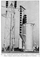
[...] After several years' operation of these neutralizers, the line was
connected into an extensive 230-kv solidly grounded system, and the use of
the neutralizers was discontinued.
In the practice of automatic reclosing, the fault is tripped off by the circuit
breaker in the ordinary manner, and then after a reasonable interval the circuit
is closed automatically. If the fault is still on the system, the breaker
opens a second time and then recloses. After the third opening and closure,
the breaker locks out. [...]
In the early days of high-tension transmission, insulator discs were frequently
cracked by heat from the normal-frequency current which followed a lightning
flashover, and burning took place on the conductors and insulator hardware
where the arc terminated. This damage came about because of the relatively
long time (30 to 60 cycles or more) required by the relays and circuit breakers
to open the circuit.
Various devices were used to minimize the effect of this arcing, such as
plain horns, spoon horns, sphere-tipped horns, insulator-tipped horns, combinations
of horns and spheres, and rings or shields. The early literature is filled
with discussion regarding the merits of these devices.
Although the various types of horns were more or less successful in keeping
the arc away from the conductor and insulator hardware, they were not too
successful in preventing the arc from traveling up the insulator string and
damaging the porcelain. In this respect the grading rings or shields seemed
to be much better, as they largely kept the arcs entirely clear of the porcelain.
[...]
Shielding by grading rings was used and is still used extensively on lines
from 115 kv to 230 kv. Theoretically only the ring at the line end is necessary
for gradin, and many lines were equipped with rings at the line end and horns
at the ground end (Fig. 9.32). However, it was found, especially on long insulator
strings, that grading was helped by a ring at the ground end as well as at
the line end. Also it was found for strings, short and long, that the second
ring helped materially in keeping the arc away from the hardware along the
string, thus saving damage to the hardware and porcelain. A 110-kv line equipped
with grading rings top and bottom is shown in Fig. 9.33.

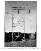
[...] With the gradual appearance of faster relay and breaker operation (6
to 12 cycles overall), the damage to insulator porcelain and hardware, due
to the short-circuit current arc, has greatly diminished, and the necessity
for rings and other devices has practically disappeared. Modern lines are
therefore usually built without such devices. In some cases of extra-long
insulator strings operating at high voltage, rings are still used to keep
the arc away from the insulators and conductors, and to prevent corona formation
on the line hardware at operating voltage. [...]
Protection of Stations and Rotating Machines
The station on an overhead line usually involves incoming and outgoing lines;
station buses; disconnecting switches and circuit breakers; power, current,
and potential transformers; and sometimes auxiliary equipment such as carrier-current
capacitors.
The station structure itself is commonly built of steel members on which
lines terminate and which support the buses, disconnecting switches, etc.
(Fig. 10.1). The power transformers and breakers usually rest on concrete
pads on the ground.

The problem of the protection of such a station resolves itself into two
parts: the protection from direct strokes, and the protection from traveling
waves coming in over the lines.
The protection from direct strokes involves shielding by overhead ground
wires, masts, or rods. If supports are available for overhead ground wires,
these may be run over the station in such a way that the station and all apparatus
will lie in the protected zone. [...]
If it is not feasible to run ground wires over the station, then it may be
possible to erect masts or rods at the corners or over vertical columns, so
that the buses and apparatus in the station will fall within the cone of protection
of the masts or rods. Such a cone may be assumed to have a base radius equal
to twice the height of the mast. [...] Fig. 10.5 is a view of a small station
protected in this manner.
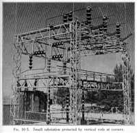
If the station is shielded from direct strokes and has low ground resistance,
the only remaining source of lightning voltage is from traveling waves coming
in on the conductors. If the line conductors in turn are adequately shielded
from direct strokes, then the source of traveling waves is usually a flashover
of the insulators and the voltage is limited to the insulator flashover value.
[...]
Sporn and Monteith, looking ahead to the need for voltages higher than 287
kv, have suggested 345, 402, and 460 kv as possible steps. They proposed insulation
levels for the range 230 to 460 kv, as given in Table 10.7, and have also
suggested line insulations as given in the table.
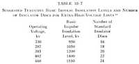
[...] With transformer banks guarded only by the flashover of the bus insulation
or transformer bushings, the insulation to ground of the majority of rotating
machines is in danger when they are connected to the transmission system through
transformers with relatively high transformation ratio.
A lightning arrester on the high side capable of reducing the incoming lightning
voltage to some 70 per cent of the bushing flashover would remove the danger
to the insulation to ground in most cases, with the exception of Y-Y grounded
neutral transformers or autotransformer banks. In the latter case, grounded-neutral
lightning arresters can be used, and if they are capable of reducing voltages
to some 56 per cent of the bushing flashover level, they will protect the
insulation to ground of many generators. [...]
This information comes from
- Rüdenberg, Reinhold. Transient Performance of Electric Power Systems.
Cambridge, Massachusetts: The M.I.T. Press (originally McGraw-Hill). Copyright
1950. LOC TK3226.R8.
The 'Preface' states:
The field of transient electric phenomena has developed through the decades
into an important foundation of electrical engineering. For the design and
operation of electrical systems it has assumed, in general, the same significance
as the regular performance in the steady state. Moreover, some of the accidental
transient phenomena, like short circuits in a network, instability of the
generating machinery, and lightning disturbances on transmission lines, have
become of such outstanding importance that the layout of modern power systems
is predominantly determined by their conditions. [...] This book deals with
the transient performance of power circuits with lumped properties. [...]
In part, this book corresponds to a German treatise by the author, on the
same general subject, the third edition (1933) of which is out of print. The
contents of this first English edition are greatly enlarged, in order to comprise
also the new developments in the field. [...]
The following information is excerpted from this book.
Introduction
In the early years of electrical engineering, power systems were designed
according to the requirements of regular sustained operation. By thorough
investigation of the materials used and by study of the properties of the
machines, apparatus, and lines in steady operation, remarkable success was
attained with respect to the magnitude of the power, th elevel of the voltage,
and the distance through which the electric energy was transmitted. However,
experience showed that with switching processes in the circuits, and under
similar intentional or accidental conditions, peculiar phenomena appeared
which could greatly disturb the regular operation of the system. Since then,
numerous investigations have endeavored to clarify scientifically these phenomena,
and to devise methods to prevent damage in the networks. [...]
Mechanical and Thermal Short-Circuit Effects
Two effects determine predominantly any destructions by short-circuit currents;
namely, the mechanical forces of attraction or repulsion on the current-carrying
conductors, and the thermal effects of the currents in the conductors. Both
these effects usually set in suddenly and with extraordinary intensity, and
sometimes display peculiar forms. Figure 1 shows the remains of a three-phase
circuit breaker after a disastrous short circuit initiated by a flashover
between its insulators. Such flashovers may occur by contacts insufficient
in area or too loosely screwed, which may produce far-flying sparks when suffering
short-circuit currents.
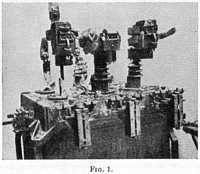
Figure 2 pictures a transformer coil, completely deformed under the influence
of a short-circuit current flowing in the coil within the leakage field of
the transformer. Figure 3 presents an instrument transformer, the insulator
of which has been burst by short-circuit effects. Finally, Fig. 4 shows, as
an extreme example, the effects which were produced by repeated reclosing
of an oil circuit breaker under remote control on a metallically short-circuited
line. The circuit breaker, together with the switching station, was blown
up.
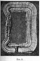
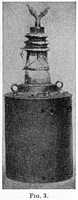

[...]
Grounded Neutral in Three-Phase Systems
[...] Figure 10 shows the grounding arc of an insulated 100-kv system of
60-amp capacitance current, as it develops after ignition by a thin copper
wire bridging an insulator. Figure 11 indicates the same event, however, after
inductive grounding of the neutral, and the very slight spark which occurs
is enlarged in the inset.

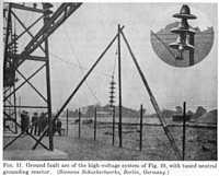
[...]
This information comes from
- Cotton, H. (Emeritus Professor of Electrical Engineering, University of
Nottingham). The Transmission and Distribution of Electrical Energy.
London, Great Britain: The English Universities Press, Ltd. Copyright 1958.
LOC TK3001.C65.
(Additional information from this book is located on the Power
Systems page, the Interference
Between Power and Telecom Lines page, the Poles
and Towers page, and the Insulator
Usage page.)
The following information is excerpted from this book.
[...]
Corona
If an alternating potential difference is applied to two wires whose spacing
is large in comparison with the diameter, and the potential difference is
gradually increased, a point will be reached when a faint luminous glow of
violet colour will make its appareance, and at the same time a hissing noise
will be heard. This phenomenon is accompanied by the formation of ozone, as
is indicated by the characteristic odour of this gas. If the potential difference
is raised still farther, the glow and the noise will increase in intensity
until eventually a spark-over will take place. If the wires are perfectly
uniform and smooth, the glow will be uniform along their length, but if there
are any roughnesses, these will be picked out by brighter illumination. With
wires only a short distance apart in comparison with their diameter, sparkover
may take place before there is any luminous glow.
If the applied potential difference is direct instead of alternating, the
two wires no longer have the same appearance; the positive wire having a uniform
glow, while the negative wire has a more patchy glow, often accompanied by
streamers if there are any rough places. It thus appears at first sight that
the phenomenon is different for the two types of applied potential difference,
but if with an alternating potential difference the wires are examined stroboscopically,
it will be found that the appearance is now similar to that with a direct
potential difference.
The above phenomena are termed corona, and an important point in connection
with corona is that it is accompanied by a loss of power, and this means that
there is a flow of current to the wire. [...]
Under normal conditions, the loss of power due to corona is of no great importance,
and consequently corona calculations do not enter directly into transmission
line design. The basis of such design is essentially financial, the most economical
line being the most acceptable. If such a line has a critical voltage under
normal weather conditions of about 10 per cent. above the operating conditions,
then it will be quite satisfactory, although Woodruff suggests that "in
a region where there are only a few storms each year on the average, it might
be wise to allow considerable corona loss on these rare occasions, so as to
enjoy the continuous benefit of the higher voltage without increasing too
much the cost of line construction". If a line designed on economical
considerations has an operating voltage near to, or greater than, the critical
voltage for corona, then either the size of the conductors must be increased,
or the spacing must be increased, thus entailing heavier towers. Either remedy
will, of course, increase the cost of the line. Alternatively, the line as
designed can be operated at a lower voltage than anticipated, but the small
choice of voltage due to standardization may make this impossible. If such
a reduced voltage is adopted, the kVA. capacity will be reduced in proportion.
Hence, as a rule, one of the other remedies will be preferable. With important
transmission lines in which a large conductor is required, a stranded conductor
of aluminium, possibly with a steel core, will be of such diameter that corona
loss will be avoided, except possibly under storm conditions.
An advantage of corona is that it reduces transients, since charges induced
on the line by lightning or other causes will be partially dissipated as a
corona loss. In this way it acts as a safety valve, and in one or two cases,
lines have been purposely designed to have an operating voltage near to the
critical voltage in order to do away with the necessity for, and the expense
of, lightning arrester gear. An objection to this scheme is that the critical
voltage is not fixed for a given line, but may vary considerably with changes
in the weather.
The disadvantages of corona are firstly, there is a definite loss of power,
although this is not important except under abnormal weather conditions; and
secondly, the non-sinusoidal corona current causes a non-sinusoidal drop of
volts, and these may cause some interference with neighbouring communication
circuits due to electromagnetic and electrostatic induction. [...]
Circuit-Breakers
[...] The general arrangement [of interrupting heads on a high-power circuit
breaker] is shown in Fig. 15.16.
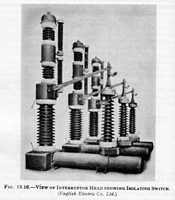
[...] The live-tank arrangement lends itself particularly to the multi-break
construction, since the interrupting chambers can be mounted one above the
other, or in Vee formation as in the 380 kV. breaker of Fig. 15.26 for an
air-blast unit.

[...] For the largest ratings, outdoor installation is usual in order to
avoid building costs. Figs. 15.31 and 15.32 show substations containing outdoor
bulk-oil, low oil-content, and air-blast circuit-breakers.
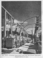

[...]
Principles of Feeder Protection
[...] [Carrier current systems] are essentially lock-in systems in which
a high-frequency current is used for the sending of the locking signal [to
prevent the inadvertent opening of one of the circuit-breakers]. This signal
can be injected into the line wires, pilot wires being thereby eliminated.
The coupling of the signal circuits to the power lines is effected by means
of large capacitors in the form of porcelain insulators [...] [which] then
take the place of the ordinary potential transformer. Line couplers of this
type are illustrated in Fig. 16.40.
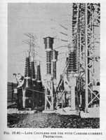
[...]
Protection Against Overvoltages
[...] In the case of insulator strings, destruction of the string can be
prevented by the provision of arcing horns and rings, while in the case of
transformers, rod gaps, called co-ordinating gaps, can be installed to protect
the apparatus (Fig. 18.25).

[...]
This information comes from
- Willheim, R.; Waters, M. Neutral Grounding in High-Voltage Transmission.
New York, NY: Elsevier Publishing Company. Copyright 1956. LOC TK3227.W5.
The 'Introduction' (by R. Rüdenberg, Professor Emeritus of Electrical
Engineering at Harvard University) states:
Throughout the last half century, the practice of design and operation of
large electric power systems in most respects has developed along similar
lines in America and Europe, based on the fact that the underlying laws of
nature are the same everywhere. One singular problem, however, has evolved
in different ways: namely, the protection of the electric system against occasional
breakdown, caused either by natural events hithero unpredictable like lightning,
or by accidental failures due to the random behavior of electric insulation.
[...] So it came about, that in the United States preponderantly the solid
grounding of the neutral point of large electric power systems was preferred
and has been technically developed with all its ramifications as to emergency
switching operations of various kinds. In Europe, on the other hand, the inductive
grounding by resonant reactors was invented and utilized, which from the outset
provided neutralization of ground fault currents and gave protection to power
as well as communication systems without the need of novel switching procedures.
[...]
The following information is excerpted from this book.
[...]
High-Voltage Systems under Normal and Ground Fault Conditions
[...]
Steady-State Voltages During Ground Faults
[...] The relative frequency of occurrence of sustained ground faults is
suitably demonstrated by the operational experience of systems with resonant
grounded neutral. The great majority of all single-phase ground faults is
found to be transient, i.e. self-clearing within a few cycles or perhaps
seconds. This is evidenced by Table 6:
Table 6 |
Name of system |
Voltage kV |
Percentage transient single-phase
ground faults |
Public Service Company of Colorado |
13.8 |
80.5 |
Badenwerk, Germany |
20 |
86 to 90 |
North Moravian Elec. Supply Co., C.S.R. |
22 |
96 |
Swedish State Power Board |
22 |
85.5 |
Wisconsin Michigan Power Co. |
34.5 |
83.3 |
Swedish State Power Board |
44 |
91 |
Swedish State Power Board |
77 |
95 |
Victoria Falls Power Co. |
88 |
97 |
Public Service Company of Colorado |
100 |
97 |
Austrian Interconnecting System |
110 |
90 |
Badenwerk, Germany |
110 |
87 |
Bayernwerk, Germany |
110 |
81 |
Swedish State Power Board |
132 |
93.5 |
Consumers Power Co. |
140 |
85 to 94 |
[...] The tendency to carry on with a sustained ground fault is very pronounced
at voltages up to 34.5 kV. [...]
Transient Phenomena in Three-Phase Systems
[...]
Initiation and Development of Ground Faults
[...] The great number of insulators and immediate exposure to lightning
surges are only two of the many reasons why overhead lines play such an
important role in the ground fault statistics of power transmission systems.
Birds try to perch on or near pin insulators, thereby reducing the insulation
clearance and causing flashovers (Fig. 74). During the migration season,
this type of fault is quite epidemic. Most seasons have their peculiar type
of ground fault trouble. During the harvest, the wind drives stalks on to
the line insulators. Ropes, kites, blasting, [and] attempts at suicide,
are other, less seasonal causes. If the line passes near trees without sufficient
margin, wind may bend brances and make twigs touch one of the conductors.
Icing causes deep sagging of the wires, sometimes right down to the ground,
sometimes to a lesser extent, but then the load may fall off along whole
spans, causing the wire to dance and perhaps touch the ground wire. In coastal
districts, salt is deposited on the insulator surface; in industrial areas,
the porcelains may be covered by thick layers of dirt or coal dust, along
which in foggy weather discharges may develop into flashovers. A surprising
fact is the regular occurrence of ground faults at sunrise.
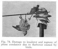
[...]
The Ground Fault Neutralizer (Arc Suppression Coil) General Theory
[...]
The Extinction of Ground Fault Arcs in Systems with Ground Fault
Neutralizers
[...]
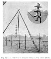
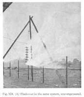
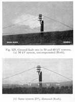
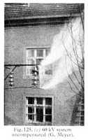
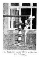
[...]
Resonant Grounding versus Dissonant Grounding
[...] The first ground fault neutralizer ever used was installed in 1917
in the German power station at Pleidelsheim where it was connected to the
alternator neutral. It was air insulated (Fig. 160 and 161). The arrangement
was otherwise the same as now in general use, thus being characterized by
a saturable core with air gaps and a tapped winding.

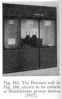
[...]
Review of Resonant Grounded System Performance
[...]
Comparison with Other Methods of Reducing the Fault Rate
[...] A theory has been presented by L. V. Bewley on the basis of which
the operational performance of various types of transmission lines can be
compared. Table 40 is taken from his statistical and analytical investigation
of 132 kV lines insulated with 9 standard discs, length of span 750 ft.,
tower footing resistance 30 ohms.
Table 40 |
Type of Line |
Ground Wires |
Flashovers expressed as % of
total [lightning] strokes |
1-phase |
2-phase |
3-phase |
Both Circuits |
Wood Pole, wood crossarms. |
-- |
0 |
.33 |
79 |
-- |
Steel Tower, single-circuit. |
-- |
72 |
18 |
8.3 |
-- |
Steel Tower, single-circuit. |
1 |
6.8 |
2 |
0 |
-- |
Steel Tower, double-circuit. |
-- |
76.3 |
19.7 |
2.7 |
20.3 |
Steel Tower, double-circuit. |
1 |
8.8 |
0 |
0.17 |
2.2 |
[...]
Design, Testing, and Commissioning of Ground Fault Neutralizers
Design of Ground Fault Neutralizers
[...]

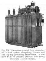
[...]
Insulators Home > Book
Reference Info > Overvoltage and Flashovers
Contact: A.C. Walker